solar
Tips, info or tricks we learned on solar along the way. We reserve the right to be wrong (we're still learning).
View our energy setup, or read about power on a sailboat.
Terms
The information below is usually found on the back of the solar panel, or in a downloadable spec sheet on the store's(or maker of the panel) website.
- Voc. Open circuit voltage. Voc is a lab-produced value of the amount of voltage the panel can produce with no load at 25º C
- Vmp. Voltage at Maximum Power. The voltage the panel will produce a maximum power output. It is the working voltage of the panel. It is the voltage the panel will supply to a battery or charge controller.
- Ipm. Maximum Current
- Ics. Short Circuit Current
- Nominal voltage. The voltage class of a circuit or system, used as a reference point for electrical systems(12 V, 24 V etc).
What to choose?
The kind of panel you choose depends entirely on the available space, and your budget. Although, someone on a small budget on a small boat may struggle, because the cheaper the panel, the larger it is. A polycrystalline or thin film panel needs to be much larger to match the output of a similarly-sized monocrystalline panel.
We can't recommend choosing flexible panels, they don't last long and will cost more in the long run. If this is the only option available to you, just be careful on where you install them(away from wave wash on deck, and make sure that the bend isn't too aggressive).
Here are the different types of panels available out there, along with their advantages/disadvantages.
Monocrystalline. Darker in color, each cell is cut from a single silicon crystal, they are more efficient overall. They yield the highest output while occupying less space, but do better in warm weather. They can last near forever, up to 26 years of peak performance. Available in hard and flexible form. A bit more expensive than polycrystalline panels.
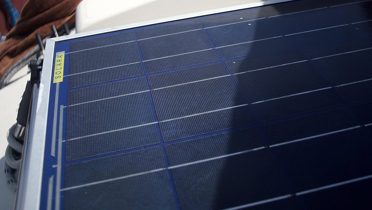
Polycrystalline. Lighter, blue in color, the cells are composed of multiple, smaller crystals. They are less efficient than monocrystalline in lower light situations, but are cheaper to manufacture and therefore cheaper to buy. Available as hard panels. They can last near forever, with at least 25 years of peak performance.
Thin film. Solid black in appearance, made by depositing a photovoltaic substance onto a solid smooth surface. The four main substances are Amorphous Silicon, Cadmium Telluride, Copper Indium Gallium Selenide, and Dye-Sensitized Solar Cells—technically all different, but they all fall under the category of thin film panels. They are less efficient, but cheap to produce. High temperatures and shading have less impact on these solar panels.
Types of coating used in flexible solar panels
ETFE( Ethylene tetrafluoroethylene). A fluorine-based plastic. ETFE were created to help make robust flexible panels. It was apparently created with high corrosion resistance and were considered to have the same long life span as tempered glass when used in the solar industry.
PET. A kind of polyester-based plastic. Affordable and light. Has a short lifespan of 5 years, due to their proneness to delamination and to corrosion. Avoid.
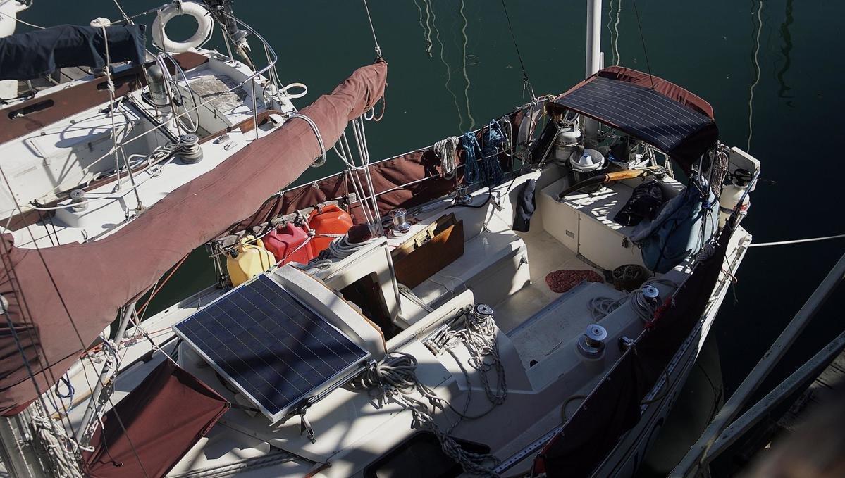
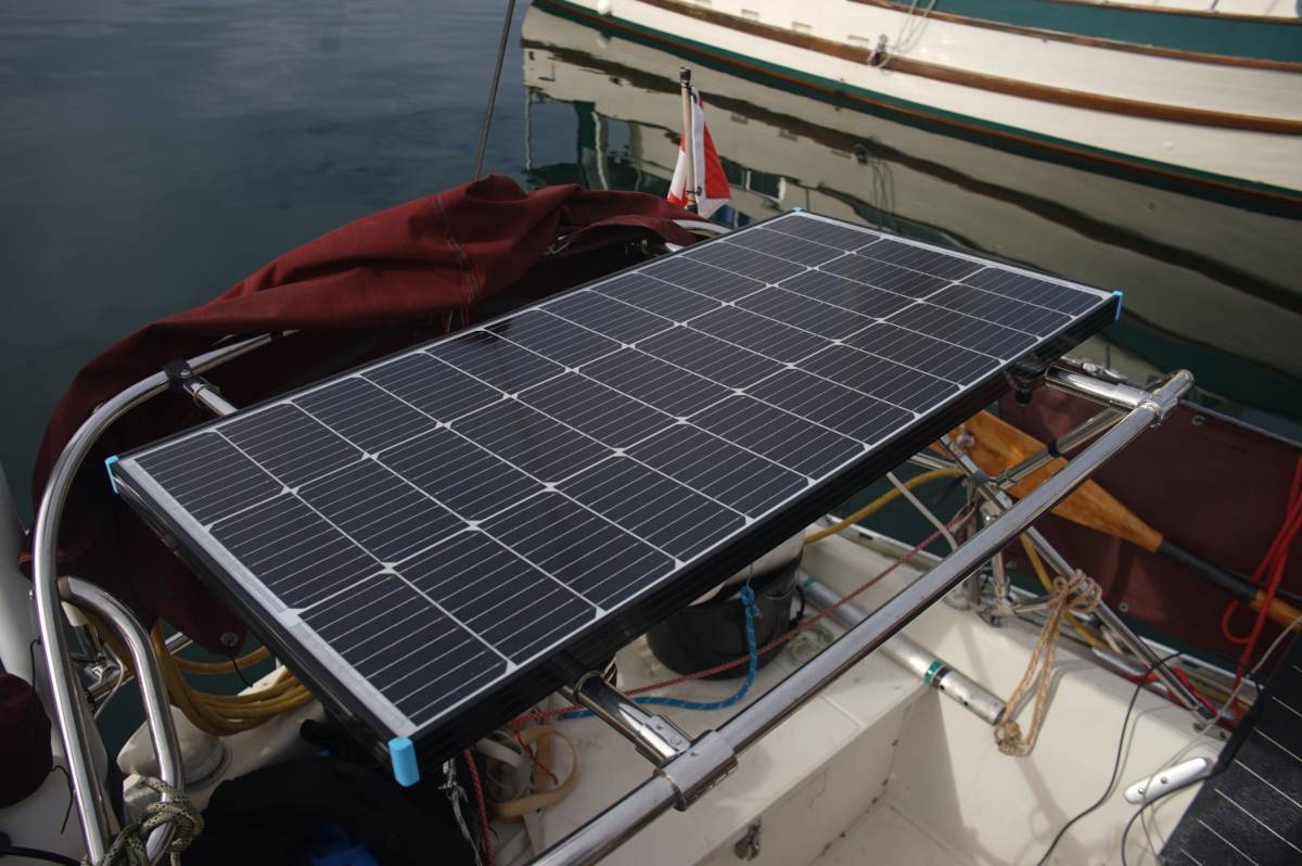
Deck installation
Install hard panels with an air space underneath to permit the panel to cool down. Warm temperatures produce a decline in the panel voltage of approximately 1V for every 12°C(22°F) to 15°C(27°F) temperature rise.
Parallel wiring
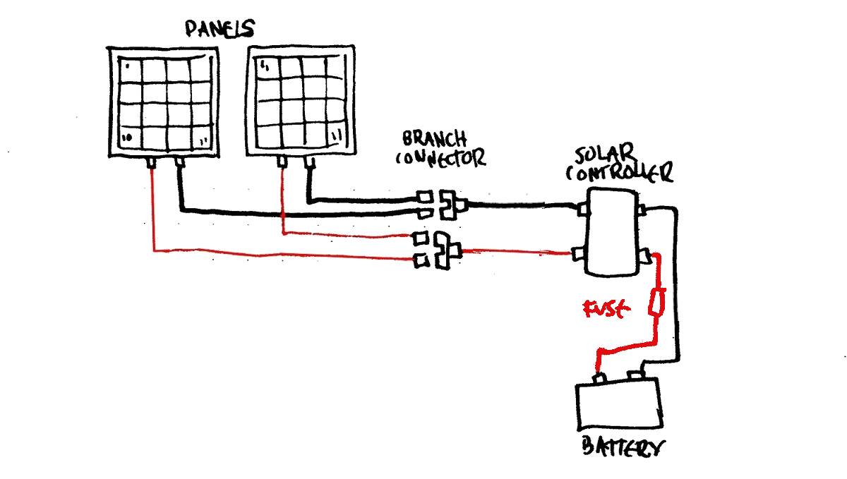
Note that the above diagram is for our boat, and sized to our system. Panels with more wattage will require additional fuses. See below to determine whether or not your system needs other fuses.
On a 12V system solar panels ought to be connected in parallel so the voltage stays the same. With panels in parallel, the amperage of each panel is added up, and the performance of one panel is not dependent on the performance of another. This is important on a boat because at one point or another, one of the panels will have shade from the mast, radar post, boom etc. Multiple panels connected in parallel offer the best performance. Note that wiring panels in parallel requires a thicker wire gauge to accommodate higher passing current.
To wire multiple panels in parallel you'll need MC4 branch connectors, or T connectors. Optionally, you can also lead wires indoors and them meet on a gang terminal.

Adding panels to a system is easy with branch connectors, this is how you connect them in parallel. A 3-way branch connector accepts 2 wires, and combines them into one, so a connector with two positives becomes one positive, and the same applies to the negative side. These two wires will in turn connect to the solar controller.
In short, things to remember:
- Voltage stays the same
- Amps are added up
- Can perform if one panel is partially shaded
- Thicker wiring
- Requires extra gear like branch connectors(or gang terminal)
Wire sizing
When it comes to sizing wires, the smaller the number, the bigger the cable.
Important to note that UL cables(AWG, American Wire Gauge) are larger than SAE(European standards). Some wires will display wire thickness in mm or inches, to find out their AWG equivalent view this table.
Example: For Pino, we calculated the round-trip distance the wires would take, which was less than 6m(20ft) with 3% voltage drop and with the NEC safety factors applied. Given that the max power that will ever run through the wires is 16.28 A, we bought some 10 AWG wire.
Example
- 2x100W 12V panels
- At 18V
- Producing 5.21 A each
- Distance to controller is 15 ft
What voltage should a solar panel produce?. The number will be indicated on the back of the panel. Another way is to estimate by counting the number of solar cells(usually available on the panel's spec sheet).
Individual solar cells produce between 0.45-0.6 V (Vmp) at 25º C. So a 36-cell 12V panel would produce anywhere between 16.2-21.6 V. The output of the individual solar cells vary due to the type and quality of the cells that were wired together.
In the sample above, we've got 2 X 100W panels, with each running to the gang terminal(or an mc4 branch connector) at 18 V, each outputting ~5.21 A. Passing the branch connector the wires are now connected in parallel, and we have to add up the amps. We now have 10.42 A, while the voltage remains the same at 18 V. The solar charge controller then takes the 18 V and regulates it down to 12 V (most boats run on 12 V systems) and will be charging the batteries at 10.42 A.
To calculate how the solar controller will regulate the system from a higher voltage — like 18 V from our example — to 12 V, use the formula below...
The current I in amps (A) is equal to the power P in watts (W), divided by the Max Power Voltage in volts (V):
I(A) = P(W) / V(V)
200W / 18V = 11 A (maximum possible current)
To properly size your system, you must apply the following safety buffers to comply with the National Electric Code(NEC) code:
Add 25% to max solar array current:
10.42 x 1.25 = 13.025 A
Apply another 25% for continuous currents:
13.025 x 1.25 = 16.28 A
The wire would need to be 10 AWG. Now that we know how much voltage and amps run at each part of our system we can start sizing the wires, and we can choose a solar controller.
To calculate the wiring gauge for your system, we recommend Circuit Wizard by Blue Sea.
The size of the wiring depends on the distance between each section, too.
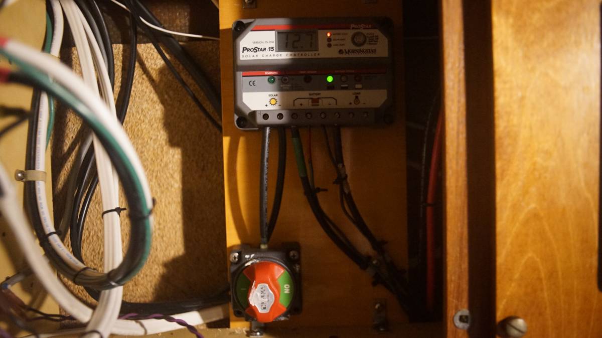
PWM solar controller
Solar panel voltages are generally higher than battery voltages (our batteries are 12 V, our panels are 18 V), which is good if the battery needs a lot of recharging, but it's not ideal if it is approaching full charge. A PWM solar charge controller monitors the battery voltage and decides how much current it can safely feed into it.
PWM stands for Pulse Width Modulation, which basically describes how it operates. Direct current from the solar panels is cut up into pulses at a certain voltage. The charger detects the voltage of the battery connected to it, and calculates the correct charging voltage to apply, which determines the charging current. The spaces between the voltage pulses are adjusted electronically. The average voltage depends on the time between the pulses.
PWM charge controllers waste any surplus voltage from the solar panel, and aren't as efficient as MPPT controllers, but depending on the size of your solar array, a PWM may be entirely fine (this is what we have).
Note: PWM controllers require nominal solar and battery voltage to be the same, eg. 12 V nominal solar with 12 V battery setup, 24 V nominal solar with 24 V battery setup.
MPPT solar controller
The most efficient type of solar charge controller are MPPT (Maximum Power Point Tracking) at 97-99%. A MPPT controller is much less efficient in low-power applications, and ought to be used with larger, more complex solar panel arrays.
For more details, see Marine How-to's mppt vs pwm guide.
Sizing a solar controller
To size a solar controller, add up the amperage from your current solar panels, and multiply that number by 25% to account for environmental factors.
Panels with a combined amperage of 10 A, plus 2.5 A (as a margin of safety) would require a 15 A controller:
10 A x 25% = 2.5 A
10 A + 2.5 A = 12.5 A
If you want to charge more than one battery bank (if one is isolated), consider one with a dual charging function. Another option is to add an auxiliary charger to charge the other bank.
Does my system require a fuse between the panel and MC4 connector?

In some cases, you may need to add a fuse between the solar panel and the solar controller (see below if it is something you need to add), and between the controller and the battery (as close to the battery as possible). Fuses are sacrificial, and protect your electricals from damages caused by overcurrent.
Here is how to determine whether or not you need fuses between the panel and the MC4 connectors for your solar installation:
Our solar arrray has a total short circuit current of 11.45 A, and the maximum series fuse rating stickers is 15 A per panel. This information is usually listed in specs of the solar panels (sometimes on a sticker on the panel itself).
If the short circuit current of the entire array is greater than the maximum series fuse rating, fuses must be placed on each wire between the panels and the MC4 connectors. A fuse ought to be installed on the positive connection from the solar controller to the battery (nearest to the battery as is possible).
If the short circuit current of the entire array is less than the maximum series fuse rating, fuses are not required between the panels and the MC4 connectors. A fuse ought to be installed on the positive connection from the solar controller to the battery (nearest to the battery as is possible). This applies to us.
It is necessary to fuse an array at the point where the panels get combined to prevent potential fires or overheating due to a faulty panel.
Read more about fusing solar arrays, especially if you have a lot of solar.
Fuse between battery and solar controller
To calculate the fuse size needed between the charge controller and battery bank match the amperage rating on the charge controller. For example, if you have a 15 A charge controller use a 15 A fuse.
To calculate the fuse size from the panel to the charge controller, add up the amperage of each panel and then add a 25% industry rule to figure out the fuse size.
For example, if you had 2 x 100 W panels that each produces about 5 A, you would use this equation:
(2x5x1.25) = 12.5 A
In the above example you would need a 12.5 A fuse, and we'd recommend a 15 A fuse (next biggest number).
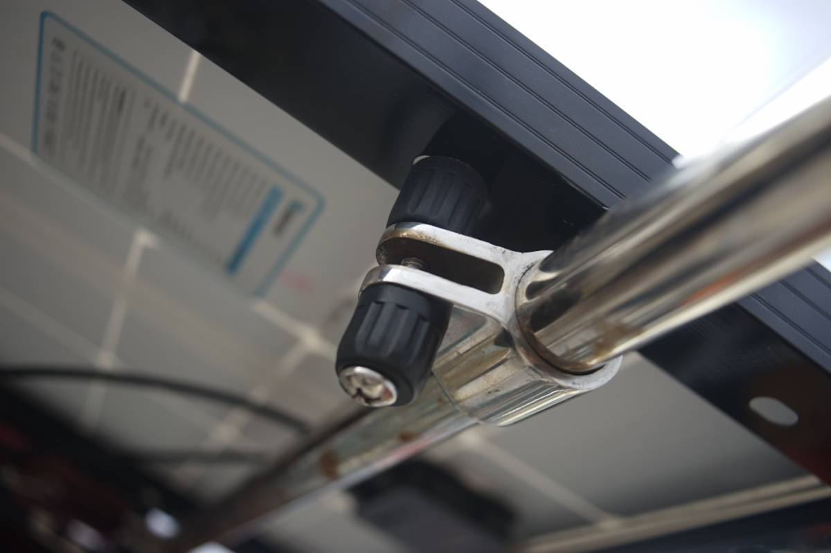
On and off switch?
The system ought to have a solar disconnect option, wired after the MC4 connectors (if any) and the solar controller. The switch should be wired on the positive side. The idea is that you can choose to turn it off if say, you'd rather charge using another source (shore power, alternator), or if you need to work on the system.
On our boat, we use a simple on/off switch our friend gave us (knob is full of paint but it works perfectly). Keep in mind to wire in a switch that is sized to the system.
Connecting panels with dissimilar voltage
Connecting two panels with different voltages, you will get voltage to lower voltage. If one panel is 17.40 V and the other 18 V, when connected in parallel the voltage will drop to 17.40 V.
Our solar panel timeline
- 04.2016 Bought one 80W (in front of mast) and a 100W flexible panels (on bimini)
- 11.2017 80W panel connections corroded, dead. Moved 100W to dodger.
- 02.2018 Bought two used hard Solara S365P36 Ultra 90W polycrystalline panels, installed both over bimini.
- 09.2018 Too much windage aft, no panels on bimini anymore. Placed one aft seat, with second stored inside underway.
- 08.2019 Plastic on 100W flexi began to part from cells.
- 06.2020 Lost 100W flexi panel & dodger after big wave in North Pacific Ocean.
- 04.2021 Sold one of two hard 90W panels.
- 06.2021 Bought and installed new monocrystalline 100W ETFE flexi panel on mini-bini.
- 01.2023 Moved solar controller, and added an on/off switch between controller and panel.
- 03.2023 Noticed ETFE panel covering was starting to part.
- 04.2023 Replaced all solar wiring. Lots of creeping corrosion. MC4 connectors arent as waterproof as advertised, got rid of them all and hardwired the panels instead. Now both panels meet on a gang terminal inside the boat in a dry space.
- 01.2025 Bought 2 new 100-watt hard monocrystalline panels to replace our existing panels, we sold the 90W panel, and we are keeping the ETFE flexi as a backup.