Introduction
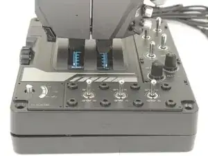
If the LEDs on your Logitech G X56 HOTAS Throttle flicker, dim, or stop working—whether individually or in entire sections—it may be due to a failing LED board. This guide will walk you through the steps to replace one or multiple LED boards to restore consistent illumination. Before beginning, ensure the throttle is not set to a lighting or power setting that could cause flickering, as some effects may be software-controlled rather than hardware-related.
If you're unfamiliar with soldering, please review the How to Solder and Desolder Connections guide and take appropriate precautions before beginning.
-
-
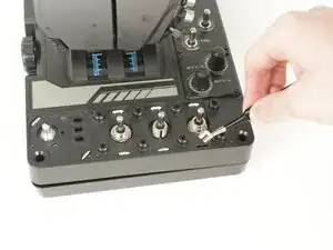
Place the throttle right side up again, using the bottom panel as a coaster.
-
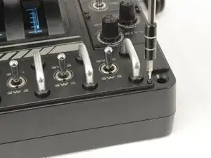
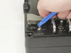
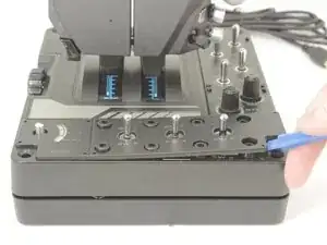
Gently pry the label plate from the body of the throttle.
-
-
-
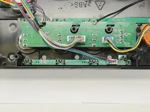
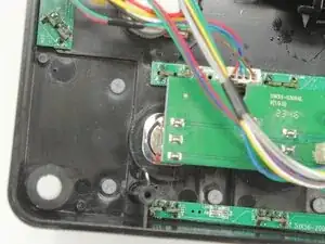
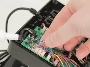
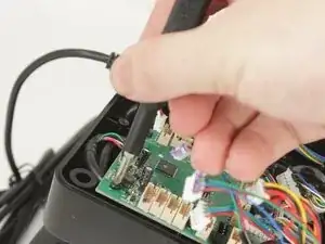
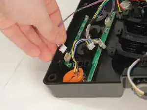
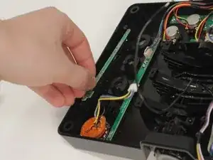
Disconnect all of the motherboard connectors by pulling them straight up and out of their sockets.
-
-
-
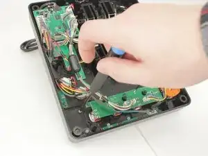
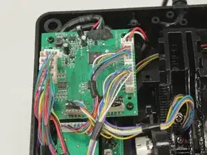
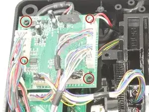
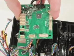
Lift the motherboard from the base plate shell, carefully making sure to keep the USB power cable unstrained.
-
-
-
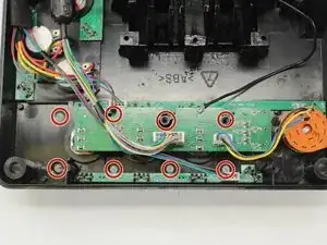
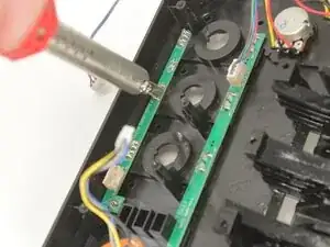
Each LED Board uses the LEDs to hold it against the base plate. It also has a single cable set to the logic and power board.
-
-
-
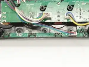
Each of the LEDs needs to be removed with a soldering iron and your choice of solder wick or solder sucker.
-
Once free of the solder, the LED must be pushed through to the front.
-
To reassemble your device, follow these instructions in reverse order.