43

I have a room with only one Ethernet cable going there, but I would like to connect two devices on it. Is an Ethernet splitter suitable for that? I am talking about something like this:

image of splitter

In theory it should work like an Ethernet hub, which only amplifies the signal, but send it to all clients (like a splitter would). I've never used it, so I need confirmation that it work or not before I'll buy it.

midlan
  • 543

8 Answers8

69

It's useful to understand what a splitter does. It turns one 8-strand ethernet cable into a what would be, essentially, a pair of sub-standard 4-strand cables that in theory should do Fast Ethernet (100BaseT/TX). Practically this might drop down to 10BaseT speeds, and you need to use a splitter on both ends for it to work. It will take up two ethernet ports on the far end. It will absolutely not work for Gigabit (1000Base) Ethernet, as that requires all 8 strands.

A hub and a switch are very different things.

A hub takes in data and retransmits it to all the ports (and I've never seen a fast Ethernet hub, let alone gigabit). A switch takes in data and switches packets only where they need to go (which is faster and more secure). This... well is a fairly dumb device that turns one cable into 'two'.

In theory it should work like an Ethernet hub, which only amplifies signal, but send it to all clients (like a splitter would). I've never used it, so I need confirmation that it work or not before I'll buy it.

Your theory is wrong, and what you REALLY need is a switch.

Journeyman Geek
  • 133,878
26

TL;DR. Buy a switch. Do not use Ethernet Splitters, EVER.

Midlan posted a link to this schematic:

Parallel Wired 'Ethernet splitter'

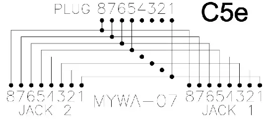
'Parallel wired' means that if you use a device like that at best you will get a load of packet collisions because you have wired the two computers (Jacks 1&2) TX pins (Pair 3, Pins 1&2) together, and the RX (Pair 2, Pins 3&6) pins together.Ethernet Wiring

Twisted pair Ethernet, 10base-T, 100base-TX, 1000bast-T, etc. all need to be connected end-to-end. At each there is a transmission (TX) pair, and reception (RX) pair. This is how a cross-over cable works.

Indeed the simplest Ethernet network using twisted pair media is using a crossover cable between two computers:

 -----------------------------------------
 |           Computer-A                  |
 |           568A                        |      
 | Pair 3 - Pin 1 - TX+ Green on White   +-------\
 | Pair 3 - Pin 2 - TX- Green            +=======|==\
 | Pair 2 - Pin 3 - RX+ Orange on White  +-\     |  |
 | Pair 1 - Pin 4 - B+  Blue             + |     |  |
 | Pair 1 - Pin 5 - B-  Blue on White    + |     |  |
 | Pair 2 - Pin 6 - RX- Orange           +=|==\  |  |
 | Pair 4 - Pin 7 - B+  Brown on White   + |  |  |  |
 | Pair 4 - Pin 8 - B-  Brown            + |  |  |  | 
 |                                       | |  |  |  | 
 ----------------------------------------- |  |  |  |
                                           |  |  |  |
 ----------------------------------------- |  |  |  |
 |          Computer-B                   | |  |  |  | 
 |          568B                         | |  |  |  |     
 | Pair 2 - Pin 1 - TX+ Orange on White  +-/  |  |  |
 | Pair 2 - Pin 2 - TX- Orange           +----/  |  |
 | Pair 3 - Pin 3 - RX+ Green on White   +-------/  |
 | Pair 1 - Pin 4 - B+  Blue             +          |
 | Pair 1 - Pin 5 - B-  Blue on White    +          |
 | Pair 3 - Pin 6 - RX- Green            +==========/
 | Pair 4 - Pin 7 - B+  Brown on White   +
 | Pair 4 - Pin 8 - B-  Brown            +
 |                                       |
 -----------------------------------------

As you can see, the TX pins on Computer-A are wired to the RX pins on Computer-B, and similarly, the RX pins on Computer-A are wired to the TX pins on Computer-B. (For simplicity's sake, I have not wired up pins 4,5,7 & 8, but for completeness they should be wired straight through pin 4 to 4, 5 to 5, etc.)

What your Ethernet Splitter is doing is just adding in a Computer-C beside Computer-B, so that Computer B&C's pins are wired together, pin 1 to pin 1, 2 to 2, 3 to 3 etc. At best, your devices will not work, at worst you will damage your Ethernet ports.

Computer-A could infact be a hub or a switch, but you still have the problem of Computer-B's and Computer-C's TX and RX ports being wired together.

Here is a wiring diagram for a simple (passive/unpowered) Ethernet hub: https://www.eeweb.com/building-a-passive-ethernet-hub/

https://en.wikipedia.org/wiki/Ethernet_over_twisted_pair

Ethernet is a digital signal, and it is not like an analogue telephone signal where you can use a splitter to add in another extension. Each little wave pattern is a packet of information that is transmitted from a TX port that is intended to go a RX port. Wiring TX ports together is going to cause all sorts of weirdness.

Instead of a splitter, your best option is to add a mini-switch, but you need to be careful with your wiring topology if you already have multiple other switches in your network.

There were other search results which mapped the two unused pairs (1&4) on 100 Base-TX to pins on 1 2 3 and 6 on the second port, so you would have to use these device on each end. However, the Ethernet wire protocol has been designed to use twisted pairs in such a way that cross-talk is eliminated between the wires. Start doing non-standard, non-compliant things, and you will end up getting non-standard, non-compliant, unexpected results.

David
  • 2,362
17

Some background:

A router or a switch connect to different devices. One device per cable. Ethernet cables usually have 8 wires in them and for 10 and 100mbit connections only 4 are used. 4 specific ones with well defined twist rates in the cable.

Splitters.

Best guess on that these do, depending on splitters I have seen in the past:

Ethernet cable has 8 wires. Sub-gigabit Ethernet only needs 4.

If we want to do ugly things then we can try to use one 8-wire cable as two 4-wire cables. This most likely will run your cable out of spec and the connection may be unreliable.

illustration of Ethernet splitter Note that these is no communication between the two NICs on the left side.

The only reason to do this is if you really need two different physical connections and only have one cable. It is an emergency kludge. At least one cable/connection is out of spec. It is not compatible with Gigabit. It is not guaranteed to work (though if you drop to 10Mbit it often will).

In almost all situations the right answer is to use a hub or a switch.

Hennes
  • 65,804
  • 7
  • 115
  • 169
1

Notice your image shows two splitters - that's because these adapters are used exclusively in pairs.

You will need two ports on your switching device, and two cables to this splitter (the combiner?) then one cable onwards through the walls. In your room you have one cable from the wall to the back of the splitter, then one cable to each device.

In contrast, if you put in a switch you would be neater and closer to best practice.

These splitters don't carry gigabit at all, and some of them can fail to negotiate 100 Mbit. Also, they won't negotiate POE either.

As an alternative, can you run more cable in the wall? Use the existing wire as a draw cord for several lengths? This is why overdoing cable runs is a good idea when the wall linings are open.

Criggie
  • 2,580
0

Depends upon what you are trying to do, If you are trying to connect two separate machines though Ethernet to the modem/router then you would need a switch(network), but a hub will just connect the two machines to each other and relay the same packets over and over, not achieving much.

Short and sweet: No, an Ethernet splitter will not work for your purpose, use a switch(they can be a little expensive)

-2

An Ethernet splitter can be thought of a type of device that isn't a hub or a switch. It is a rather simple device that actually does nothing but connect two pairs of 2 Ethernet cables to a single Ethernet cable. If you don't trust Ethernet splitters then you can actually build a cable that does the exact same thing.

A splitter works by taking two physical Ethernet ports and sending both connections (which must be limited to using 100mbps speeds) though a single cable. A splitter doesn't connect both ports together in any way. It keeps both ports isolated unlike hubs and switches.

Here is a diagram to show you how a typical Ethernet splitter system works. Ethernet splitter wiring diagram

Basically, 100Mbps Ethernet only uses 2 out of the 4 pairs in a standard Ethernet cable unlike 1Gbps Ethernet which uses all 4 pairs. In 100Mbps Ethernet, 2 pairs simply get unused. In theory, if you were working with 100Mbps Ethernet, you could use the 2 unused pairs for almost anything. PoE is one way you can make use of the two unused pairs (PoE only works with 100Mbps connections for this very reason). Splitters are just another way of making use of the two unused pairs since you can fit entirely another 100Mbps connection since the connection requires only 2 pairs.

Unfortunately, there are several downsides with using splitters:

  • You'll be limited to 100Mbps speeds even if you connect it to hardware capable of 1Gbps speeds. Each connection lacks the necessary pairs to do 1Gbps speeds. Hardware that does 1Gbps speeds will see that 2 pairs are missing and auto-negotiate a speed of 100Mbps.

  • You still need 2 free ports on your existing switch/router. Switches/routers only provide one connection per port. Trying to use a splitter to turn one connection into two won't work since that's the job of switches/hubs which clearly, a splitter is not either of. If you attempt to use this two turn one connection into two, I see two possible scenarios: Only one device will receive a connection, or, the port on the switch/router will fail to work properly with both devices connected.

  • Any cable you connect to the splitter will count towards your total cable length. However, since a splitter has 2 physical connections, you have two cable lengths instead of just one. Theoretically, splitters don't amplify signals so your maximum cable length will not be extended.

Now to answer your question: It will work but only under certain conditions. If you need more than 100Mbps speeds then either run another cat 5e cable to your room or buy another switch. If this is not possible then you'll have to deal with 100Mbps speeds. Also, if you have only one spare port on your router/switch, this is not going to work for you.

-2

Speaking of the concept, more than just a connector...

Every ethernet network connects terminals via a splitter, so to speak. A splitter is just a parallel configuration of devices.

A daisy-chain configuration connects many devices in parallel to the one host.

A series configuration goes terminal to terminal, with each connected in parallel. Typically requires less overall cable length.

All ethernet devices on one network are connected together, in this simplest way. All terminals must be connected to the same network wire.

The ethernet philosophy is that each terminal listens before transmitting, and also listens during transmission, to detect collisions (two terminals transmitting at same time, interfering). If a collision occurs, each terminal backs off and waits a short random time (milliseconds), and then simply tries again, as often as necessary.

A switch could be used to remove other traffic from the terminal, and to improve bandwidth on that one wire, but it is not required to do so.

WayneF
  • 107
-2

Cat.5e and even Cat.7 cables regularly come as UTP, and when these get bundled you will have individual pairs just a mm from each other, and splitters like these are seen (as devices or 4+4-Wire use of old cable plant at the patchbay) used in professional installations.

Downgrading to 100Mbit is expected behaviour (DO use a true 100Mbit switch in a permanent installation, you want something that auto-negotiates to 100FDX (100 Mb full duplex), a gigabit switch configured to 100Mbit usually will not, leaving other devices confused) - if it DOESN'T something is odd, either all devices on that cable support 1000BASE-TX -- which can work on two wires but needs even higher grade cable, and is uncommon in most equipment.

1000Base-T is what we commonly know as GBe, and it needs 4 pairs period; if a device claims it has a 1000Base-T link on 2 pairs it probably has mis-negotiated or not negotiated the link at all, and won't work. The PROBLEMS start when whoever designed that splitter made different assumptions than who made/installed your cables. Once you use wires from different physical pairs for one logical pair, all the electric "magic" of twisted pair cable is gone, and it will behave like rotten old baling wire instead of like a high spec rf cable.

David
  • 2,362
rackandboneman
  • 780
  • 4
  • 6