1

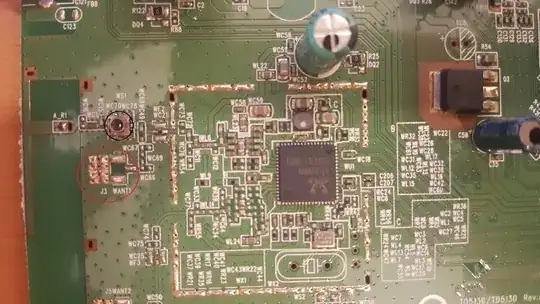
I want to add an external WiFi antenna to a Speedtouch TD5130 router I'm using as AP in order to try increase WiFi coverage range. The thing is I've disassembled the router and then I've seen it does not incorporate any WiFi antenna nor the connectors to add one. It looks pretty straight forward but as i don't have previous experience on the field i would like to know if you think that just soldering an U.FL Connector and then adding a female U.FL to RP-SMA wire would make it possible to add the desired WiFi antenna. I would solder it at the red circle.

Speedtouch TD5130 PCB

enter image description here

Looking at the picture, do you think the previous setup plan would work? I also suppose the signal pin should point East, right?

Also, I'm wondering if any one knows what's the part inside the black circle and what's used for?

Thanks a lot!
peris
  • 183

1 Answers1

3

The part inside the black circle is a connector (of U.FL type) with a built-in switch. When a properly mated part is plugged in, the switch disconnect the signal path from internal PCB load/path, and re-route it into the attached cable. It is mostly used for debug/calibration/certification purposes.

To use the U.FL non-populated spot, it is a challenge, because the connector is surrounded with non-populated L-R-C tuned network, and values of this network are unknown, unless you have full design documents. More, changing on-board RF path will likely require some configuration changes at firmware level, so your project has a very small chance to succeed.

COMMENT: The design apparently uses a printed circuit antenna, in A_R1 area. The most promising path is to use WS1 connector-switch with external antenna. However, this is still a challenge, since all impedance matching and antenna tuning will be required. Without good RF instruments it will be difficult.

Ale..chenski
  • 13,235