26

I recently bought a house with RJ-45 and RJ-11 on one wall plate, and coax for TV on the other plate in a single box in each bedroom. I opened one up, and it looks like they did not run individual Cat 5 from each one but instead have Daisy chained from outlet to outlet, using a single Cat 5 for both the telephone and the internet. It terminates into a single Cat 5 in the garage which is currently wired to nothing, no connector or anything.

From some research online, it seems like this should work for 10/100 in theory, but clearly not the ideal way to set it up. I don't care about the telephone RJ-11 but I would like to get the Ethernet working if possible.

What I'm trying to figure out is how to attach an RJ-45 end to the cable in the garage since not all wires are being used. Do I simply put the same colors in the same location on the RJ-45 and the switch I will plug it into in the garage will know what to do with it? Also will a simple 8-port switch behind my Google Wi-Fi router be enough to negotiate all of the outlets?

I've attached a picture of it below; hopefully it shows enough. It does appear they only used two wires for Ethernet, but I need to take a closer look since I don't think it's possible for that to work.

Any suggestions are appreciated!
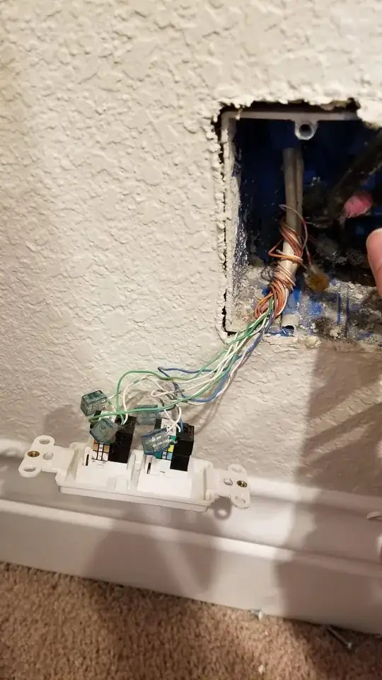
RJ45 and RJ11 wire exposed

Toby Speight
  • 5,213
Shygar
  • 383

5 Answers5

48

That's not wired for Ethernet at all. Don't be fooled by the presence of an RJ-45 and Cat5 cabling. They wired them both for analog telephone even though only one of them is RJ-11 (you can plug an RJ-11 telephone line cord into an RJ-45 jack and it will fit "okay", and make good contact with the middle pair or middle two pairs). They're using the green pair for line 1 and the blue pair for line 2 (or vice-versa).

You're almost certainly going to have to pull new Cat5 (or better) in order to wire those RJ-45's for proper Ethernet. Ethernet requires point-to-point connections, no daisy-chaining. No extra jack in the middle of a cable.

Spiff
  • 110,156
15

You may get away without pulling new wires, depending on what you want to achieve.

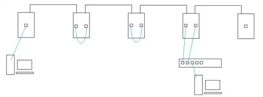
You can replace the current mixed sockets with 2 Ethernet sockets, each fully connected to one wire: one to the previous room and one to the next room. Then, in every place you're not intending to connect a computer, you link the 2 with a short patchcord. This way, you'll get a single "bus" running through your house. Wherever you want to tap into that bus, you replace the patchcord with 2 cords and a switch.

Depending on how many switches you'll need, it'll eventually be more expensive than simply rewiring entire house. However, a "tappable bus" is more elastic if you're not sure where the central hub should be, because all sockets are equal.

smth like this

Agent_L
  • 1,790
6

The only way you could make that work without pulling new wire would be to crimp those wires into proper ethernet and have a switch at each point in the line that takes the input and then has a downstream port continuing on the other wire in the box to the next jack. But that is really a terrible idea. I would only do that if I was only going to use it in maybe one or two spots. If you are lucky maybe it's cat 5e so you could get gigabit out of it. If that was the case the performance might be ok. Remembe that this is a hack. Not ideal at all.

You really need to pull new wire or consider a powerline adapter solution. That or just rely on wifi.

2

There are some Poe repeaters / 3 port switches what would give you this "drop and continue" / daisy chain of the multiple ports without needing a power outlet on each. Something like the Dahua pft1300 Its a good idea for "bus" type installations with a single Poe injector at the begining.

0

Probably it is not daisy chained, On any CAT5 cable only 4 wires are used, other 4 wires are doing nothing other than future proofing or possibly shielding other wires. From my experience you can use one Ethernet cable to connect two computers or devices, so by pulling 2 cables you can cover 4 rooms, that's how network splitters/multipliers work.

Look at how the wires are connected at the other end and match this end to them.
There are 2 standards and they are colour coded as:

OK, I am not allowed to embed images (new user).

EIA/TIA-568A:White-Green , Solid-Green, White-Orange, Solid-Blue, White-Blue, Solid-Orange, White-Brown. Solid-Brown.

EIA/TIA-568B: White-Orange, Solid-Orange, White-Green, Solid-Blue, White-Blue, Solid-Green, White-Brown, Solid Brown.

RJ45 Connectors

If the installer/engineer did not follow standards then you need to follow the installer and match colours at both ends. Borrow RJ45 crimping tool, Network punch tool, network tester and buy some RJ45 ends, it is not that easy (few trials and fails) but you will enjoy the end result if you are successful in doing it, I hope it works for you! Good luck!