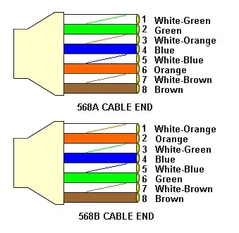
I wonder if I can solder another wire to white #7 (ground) and crimp the cable again
Unless you have a great deal of knowledge about the process, never solder network cables. By the nature of this question, you do not have anywhere close to the required level of knowledge.
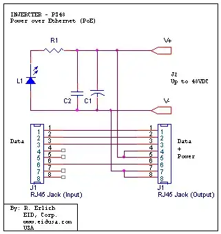
I found several PoE cable DIY videos and they just solder + and - wires from a power adapter to white-blue/blue (+) and white-brown/brown (-) wires of an ethernet cable. To me, that looks similar to what I want to do.
People making online videos may have the knowledge required to do so properly. Unfortunately many such videos are done by people like you who "think" they found a great solution and want to share it with the world without knowing why what they are proposing is a bad idea.
Not sure which videos you refer to or if you are referring to the properly (maybe you misunderstood what they were doing or I misunderstood what you are trying to pass along), but the description you provide would indicate that the videos in question are in the second video category.
I often think of these videos as the "blind leading the blind" and following their example is simply bad. Ask an expert/knowledgeable professional in the field and respect their advice.
Will such scheme damage my video recorder or camera? Will it work or it's a way to make a short circuit?
Since the device you list in question is standards compliant, it expects to be connected to a standard connection. Your fix is not standards compliant so how a device will respond is a significant question mark.
Could it be damaged? Sure. Could it short circuit? Possibly, if not likely. In any case, simply don't do it.
I crimped RJ-45 connectors on both ends so that dead wire became #8 (ground). I expected that 1 ground wire could be enough to make PoE work. My naive approach didn't work.
There is no "ground" wire in a network cable. That isn't how things work. The pairs are used as pairs for a purpose. Feel free to look into balanced-pair/differential signalling for more detail if you want more background.
Looks like swapping 6 and 8 wires works fine and there is no need to swap pairs.
Looks like you took good advice and promptly ignored it. Sure it works, but now you have split pairs and introduce a significant amount of crosstalk between the circuits (i.e. "pairs"). There are sound electrical reasons for the use of pairs and now you have violated these.
So let me say it again. Swap your damaged 3-6 pair for either the 4-5 pair or the 7-8 pair. Do not simply swap a single wire. Personally, I would then omit the old 3-6 pair and the unused 4-5/7-8 pair and only use two pair in your termination (so you have one pair terminated to 1-2 and one pair terminated to 3-6). Mark both ends of the cable as non-standard to help avoid misunderstandings/problems in the future.
Video recorder. POE: 8 ports (IEEE802.3at/af). Power consumption: PoE: Max 25.5w for single port, 80w in total
IP camera. Ethernet RJ-45 (10/100Base-T)
Assuming your Video recorder is driving the data/PoE to the camera and it is listed as IEEE802.3at/af, then I would assume your camera is as well. Of course, my assumptions could be wrong in which case you should get standards compliant equipment.
The 802.3af amendment defined two modes of operation, mode A (end span power source) and mode B (mid span power source). The two modes of operation primarily differ in the pairs that were used to provide power with mode A using the same pairs as the data and mode B using the unused pairs on a 10/100 Mbps connection. Compliant devices to be powered by PoE must be able to accept either mode.
Since the description you provide indicates your video recorder is acting as a switch, which would be a end span power source and should be using mode A. As such you should now be fine using the two pair cable as described above.
Note: you will not be able to get 1000 Mbps or 802.3bt to work on such a cable and it will need to be replaced if you need to implement either.


