5

The transmission time can be defined, as per Wikipedia, as (for a digital signal):

"The time from the first bit until the last bit of a message has left the transmitting node."

Thinking about digital signals, the tranmission time corresponds to the total duration of the whole packet. The data is pushed onto the wire from the send buffer. The amount of time individual bits of a packet should wait in the send queue (buffer) is another kind of delay that is called queuing delay, thus I am excluding it for now.

My question is this: What exactly is transmission time a function of? For example, we can say that the propagation delay is a function of a fraction of the speed of light and the distance between the connected nodes, the processing delay is a function of the processing speed of the CPUs, FPGAs etc. However, the transmission time seems to be loosely defined in terms of these functional relations.

Since queuing time is a separate kind of delay, we should think that the data that will be pushed onto the wire have already got past the queuing time, thus, the only work to do is to push the data onto the wire. The question I ask also takes the form: "What physical reason(s) prevent the data to be pushed onto the wire immediately?".

Of course, it seems it cannot be pushed onto the wire immediately, and it is not intuitive at all, but why? Is it the distance from the physical location of the send buffer to the starting end of the wire? Is it some kind of limitation that the PHY protocols are able to enforce through different limitation mechanisms (e.g. see: "...Many Ethernet adapters and switch ports support multiple speeds by using auto-negotiation to set the speed and duplex for the best values supported by both connected devices.") ? If so, what are these mechanisms on the hardware level? Is it the sampling rate of the clock of the node? Which one(s) of these would be likely to make the biggest impact on the transmission time?

I know that not every PHY protocols are able to handle high transmission speeds (e.g. Comer, D. E. (2008). Computer Networks and Internets 5th Edition: "Asynchronous serial interfaces commonly will support bit transmission speeds of up to 230.4 kbit/s."). As far as I understand, there is a limitation caused by the cabling and physical layer itself, however, I would assume the answer lies in a combination of the properties of the sending node and the physical connection interface on the NIC.

By the way, please do not tell me that it is a function of the packet size and bit rate, since it eventually comes down to saying that "Period is high, but why? Because frequency is low!", which is meaningless.

I may have skipped some sources that may be giving information on this, however, could not find any.
3 Answers3

17

Thinking about digital signals, ... The data is pushed onto the wire ...

What you refer to as (digital) data has to be represented as analog electrical signals for transmission. The real world is analog; only the information is digital. That digital (i.e. quantized) data cannot exist in the real, analog (i.e. continuous) world (unless you're studying sub-atomic particles, where quantum physics take over). It has to be represented by an analog signal. (A "digital signal" is a misnomer; it really means digital information conveyed by an analog waveform.)

All waveforms have continuous rather than discrete values, and are therefore analog. A waveform cannot be at one discrete voltage level, and then instantly change to another discrete voltage level. A digital signal would only have two levels, e.g. 0 and 1. A state of 1/2 is never permitted. But it's impossible to generate such a signal in this analog world.


Typically a combination of amplitude, phase, and frequency are employed to modulate digital information into an analog waveform. The simplest "digital" signal, the logic signal (e.g. as used in TTL and CMOS), uses just amplitude modulation to represent logic levels/states 0 and 1. The logic states are represented by, not specific voltage levels as you would expect for a true digital values, but, as a concession to the analog world that the signal has to operate in, voltage ranges (i.e. a continuum) for each logic state.

Every logic input is a very simple analog-to-digital converter. When the input is sampled (triggered by a clock signal), a sampled voltage in the low-voltage range is interpreted as logic 0. But if the sampled voltage is in the high-voltage range, then a logic 1 is "read". All of this analog-to-digital conversion is simply treated as as logic or digital input, and textbooks always use perfect square pulses to represent changes in logic states.

RS-232 is somewhat similar to TTL & CMOS since both use simple amplitude modulation. But to improve transmission capability, RS-232 uses a negative voltage range for a logic 1 and a positive voltage range for a logic 0.

Ethernet gets more complicated, and depending on the speed standard, some will use multi-level pulse-amplitude modulation.
Whereas TTL/CMOS and RS-232 have a one-to-one correspondence of each (analog) symbol represents only one bit (for two possible digital values), there are modulation schemes that have the symbols representing more than a single bit (for 2^N possible digital values).


To perform "data" transmission, the output voltage of the transmitter must be modulated. Although that voltage change will travel down the wire at the speed of light, that voltage change is opposed or promoted by the capacitance and inductance of the wire, and attenuated by the resistance. Then the signal can arrive at the receiver distorted and with noise.
The anticipated distortions in the signal constrain both the rate the voltage can be modulated for transmission of each symbol, and the rate that the signal can be reliably sampled for accurate reception of each symbol. Those constraints (with safety margins) become maximum transfer rates.


ADDENDUM

If these "digital signals" are really analog signals modulated with digital information ...

There is no "if".

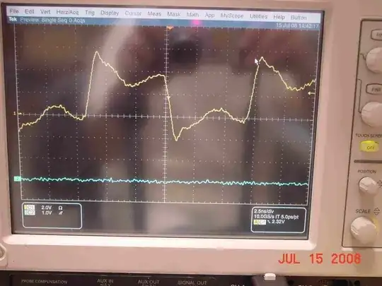
Below is a revealing high-bandwidth (10 GHz) oscilloscope capture of a CMOS (3.3V logic) "digital" signal on a PCB with an impedance mis-design.

enter image description here

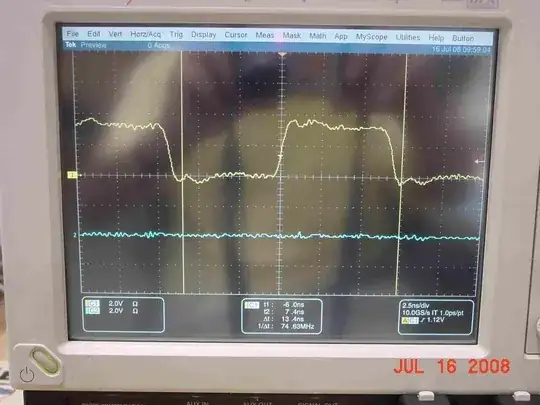
That same "digital" signal with a damping resistor in the circuit to "correct" the impedance issue.

enter image description here Imagine that!
A "digital" signal is affected by the circuit!

But it still doesn't look like those perfectly squared-off signals in textbooks. And it never will (nor does it have to), because this is the real world that is analog.

sawdust
  • 18,591
16

In your first paragraph you say it is the time between sending the first and last bit, which is correct, then you completely dismiss that as "the queue" in your second paragraph which is the wrong thing to do.

You simply can't send every bit of data down the wire at the same time and assume they are all received instantly.

The propagation time might be near the speed of light, but you need a time period where that bit is "held" on the wire for the receiver to detect whether it is a 1 or a 0. That hold time is a factor of the rise and fall time of the sending electronics, and the sensitivity of the receiving electronics and the clock rate that those two devices use to synchronise data rates with each other.

There is a queue or buffer before the data is sent out, but the wire is also a queue of data that means that an entire packet is never transmitted instantaneously at the speed of light, there is a delay for every single bit of data.

The total delays for every bit is what constitutes the transmission time.

Mokubai
  • 95,412
9

What exactly is tranmission time a function of?

The number of symbols in the message, and the symbol rate (symbols/sec, or baud).

The amount of information we can reliably transmit per second is given by the Shannon-Hartley theorem as a function of the bandwidth of the channel, and the signal-to-noise ratio on the channel.

Bandwidth is limited by a combination of physical factors (higher-bandwidth transceivers, amplifiers, etc. are harder to build than lower-bandwidth ones, transmission lines become lossy at higher frequencies, etc.) and social ones (say you're building a radio-frequency device, you have a legally allocated channel you're allowed to operate in, and that channel has a certain bandwidth).

Signal-to-noise ratio has a similar mix of factors: noise will always exist, thanks to the laws of thermodynamics, and signal power is limited by a combination of practical problems (cost, size, heat, battery life, blowing up the device) and regulatory limits.

So in any given real-world scenario you have a certain amount of bandwidth that you have to fit within, a certain amount of power that you're able to provide, a certain amount of loss between point A and B, and a certain amount of noise that you have to tolerate — all while limiting the number of errors to X%. Given all of those constraints, you hire an engineer, and they come up with a code (a way to turn the bits of a message into symbols) and a modulation (a way to turn those symbols into something physical like the phase or amplitude of an electrical signal) that meets your requirements. Given that, you now know: a message of N bits is encoded as M symbols, and M symbols take t seconds to transmit. If you want to go faster, then some part of your design constraints have to change, and the design has to change with them. And if you ask for too much, then your engineer says "I cannae change the laws of phusics!"

hobbs
  • 1,492