9

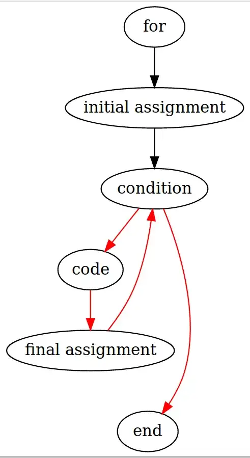
I have a very simple graph:

digraph G {
  "for" -> "initial assignment"
  "initial assignment" -> "condition"
  "condition" -> "code" [color=red]
  "condition" -> "end" [color=red]
  "code" -> "final assignment" [color=red]
  "final assignment" -> "condition" [color=red]
}

enter image description here

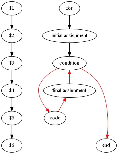
However, the nodes must be drawn in a specific order, from top to bottom. (The red arrows would be red because they defy this specific order.)

One way to do so is:

digraph G {

  {rank = same; "$1"; "for"}
  {rank = same; "$2"; "initial assignment"}
  {rank = same; "$3"; "condition"}
  {rank = same; "$4"; "final assignment"}
  {rank = same; "$5"; "code"}
  {rank = same; "$6"; "end"}

  "$1" -> "$2" -> "$3" -> "$4" -> "$5" -> "$6"    

  "for" -> "initial assignment"
  "initial assignment" -> "condition"
  "condition" -> "code" [color=red]
  "condition" -> "end" [color=red]
  "code" -> "final assignment" [color=red]
  "final assignment" -> "condition" [color=red]

}

enter image description here

However, this displays those extra nodes on the graph, and I'd rather not have that. How can I define nodes and edges without having them drawn?

(I could define the edges to be white, the node text to be white, etc., but graphviz would still allocate space for them and this wouldn't work on transparent png images. Also, layers don't work for all output formats such as .png and the space required for these nodes is still allocated. Let's not consider these solutions.)
Mawg
  • 4,603
badp
  • 3,797

4 Answers4

4

Stephen North, author of Graphviz, suggests using [style=invis]:

digraph G {

  {
    node [style=invis]
    edge [style=invis]
    "$1" -> "$2" -> "$3" -> "$4" -> "$5" -> "$6"    
  }

  {rank = same; "$1"; "for"}
  {rank = same; "$2"; "initial assignment"}
................................................................................

output

This doesn't fully solve the problem as space is still allocated for those bits and pieces, but I have to guess it's as good as it gets.

badp
  • 3,797
4

Why not using the nodes themselves for suggesting a specific ordering?

digraph G
{
  {
    edge[style=invis]

    a[label="for"]
    b[label="initial assignment"]
    c[label="condition"]
    d[label="final assignment"]
    e[label="code"]
    f[label="end"]

    a -> b -> c -> d -> e -> f
  }

  a -> b -> c
  c -> e [color=red]
  c -> f [color=red]
  e -> d -> c [color=red]
}
cYrus
  • 22,335
2

Just add an hidden relationship to your first example, so that "end" is ranked as being after "final assignment":

  "final assignment" -> "end" [style=invis]

So it becomes:

digraph G {
  "for" -> "initial assignment"
  "initial assignment" -> "condition"
  "condition" -> "code" [color=red]
  "condition" -> "end" [color=red]
  "code" -> "final assignment" [color=red]
  "final assignment" -> "condition" [color=red]
  "final assignment" -> "end" [style=invis]
}

enter image description here

0

Graphviz provides two edge attributes: dir = back and minlen = 3 that can be applied to produce the desired graph without having to use the hidden nodes and edges to force the node rank explicitly. To generate the graph requires additional bookkeeping, but this may be encoded in the source model and easily available.

the dir attribute is used to reverse the logical sense of the edge without changing the hierarchical ordering of nodes, and minlen forces the minimum length (in node ranks) of an edge.

digraph Critical {
  "for" -> "initial assignment"
  "initial assignment" -> "condition"
  "condition" -> "code" [color=red]
  "condition" -> "end" [color=red, minlen = 3] 
  "final assignment" ->"code" [dir = back, color=red]
  "condition" -> "final assignment" [dir = back, color=red]
}
Pekka
  • 171
  • 5