2

I have been reading a lot about IRQs, and it seems there is conflicting and out of date information. Some of it dating back to Windows 95. Here is what I'm confused about.

  1. Are both software interrupts and hardware interrupts managed and dispatched by the interrupt vector table. If not how are then controlled differently.

  2. I read there is a difference between PCI mode IRQs and ISA mode IRQs, is this true? If so how do you set the mode, and how do they function differently?

  3. Now that we have PCI express, do they use PCI mode IRQs (if they exist), how do they work (interrupt wise).

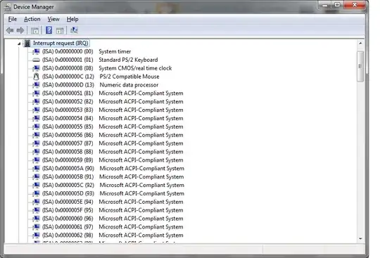
EDIT 4. Looking at this picture it appears that are many IRQs and that they are mapped to memory. What are the implications of this? There are way more than 16 IRQs. I know that APIC allows for more, but this many?

enter image description here

Thanks in advance :-)

rubixibuc
  • 2,212

1 Answers1

2

There aren't different modes, there is different hardware on the old ISA bus and the PCI bus. The ISA bus provided 16 IRQ lines on the bus that devices could use to signal for attention. The programmable interrupt controller ( actually a pair of cascaded 8259A chips ) responded to these lines by prioritizing them and signaling the CPU when one was active. This caused the CPU to invoke an interrupt service routine. IRQs 0-7 triggered int 8-F, and IRQs 8-15 triggered int 70-77. Interrupts could also be triggered via the software int instruction, and caused the CPU to call a routine pointed to by the corresponding slot in the interrupt vector table.

Instead of 16 IRQ lines shared by all devices on the bus, PCI provided 4 different IRQ lines to each slot on the bus named INTA-INTD, allowing each device to have up to 4 different IRQs for its own use. In practice, devices only use INTA, which the hardware routes to specific IRQs.

The numbers you see in the image are not memory addresses, they are simply the hexadecimal representation of the IRQ number.

The APIC supports 256 interrupt vectors.

psusi
  • 8,122