5

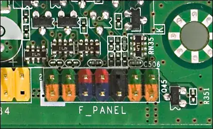
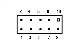
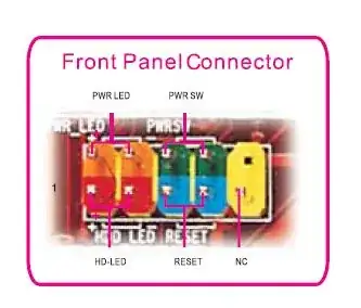
I had to exchange the case for an Acer Aspire M1201. The motherboard used in that build is an Acer RS740DVF. The trouble I'm having is that neither could I find a service or user manual for that motherboard, nor are the front panel pins labeled on the board itself. They are color coded though:

enter image description here

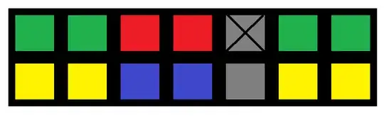
What is grey in the schematic is actually colored black on the board.

Is there a safe way to identify which pins are used for what purpose? The case I'm using is a Sharkoon MA-M1000; the front panel wires are Power LED, HDD LED, Power and Reset.

Also, what is the worst that can/is likely to happen if I attach the wires wrongly? Will they simply not work, or is it possible that I damage the hardware?

G. Bach
  • 315

4 Answers4

7

Ah. Looks like it's a Foxconn RS740M03A1-8EKRS2H. Google will verify, but here is a source.

Pin layout can be found here. The green/yellow all the way to the right aren't defined. Sorry this is the wrong Foxconn model, but the pin layout is the same, so we're in luck!

This page has the manual, I think. Anyway, the front panel layout is like this:

enter image description here

enter image description here

HDD LED     1 (+), 3
Power LED   2 (+), 4
Reset SW    5 (+), 7
Power SW    6 (+), 8

Switches don't really matter, I don't think, as they are switches. But just in case, positive on 5 and 6.

In general, this is what Foxconn layouts are described as in the manuals -

enter image description here

Raystafarian
  • 21,963
  • 12
  • 64
  • 91
3

While the list above covers most of it, it does not cover the fact that the OP is listing a 14 pin on the board for the front panel of the Acer RS780M03G1-8ekrs2hm.

Acer rs780m03g1-8ekrs2hm

This is the pin assignment:

  • on board pin 1,3 Orange from front panel wires are Red+,White- (HDD Led)
  • on board pin 2,4 Green from front panel wires are Green+,White- (Power Led)
  • on board pin 5,7 Blue from front panel wires not present could be reset
  • on board pin 6,8 Red from front panel wires are Blue+,White- (Power switch)
  • on board pin 9,10 Black from front panel wires are not present(Just to make sure the block is connected properly)
  • on board pin 11,13 Orange from front panel wires not present
  • on board pin 12,14 Green from front panel wires are Green+,Orange- (Lan Led)

The names may not be listed on the block or the main board but if you pull off the front panel and remove the wires\what connects them to the panel, you will find the labels.

The harness part number is M.351003F00A-GY0-G

HackSlash
  • 5,015
1

The pins configuration described above for the Foxconn RS740M03A1-8EKRS2H worked for the front panel of an Acer RS880M05A1 motherboard, although there was an aditional jumper (2 pins) on the right of the front panel pins block, as it is show in the first posted picture of the Foxconn layout.

Thank you!

1

Providing the pin number (ie, which is pin 1) would be more helpful since most mobo manuals would illustrate pin-outs by numbers. But on most mobos, red would be hard disk led, blue is reset switch, green is power led (not sure which one on your picture above). You could try to momentarily short out any of the adjacent yellow pins to see which one would power on the computer (power switch connector). Also note that there are polarities on the led connectors.

miggy
  • 94