I just bought a cheap Thunderbolt to VGA conversor, for a macbook pro. It didn't work at all so I decided to open the case. I found a silicon lump and most of the cables just hanging there.
Just as an exercise, I want to sort out which cables I need to solder onto which pins. Here are some pictures with what I got.
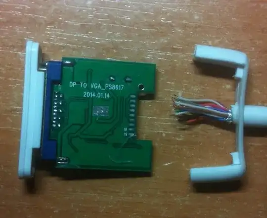
I've looked for VGA pinout and Thunderbolt pinout. Also found this link about Apple's MiniDisplay port, but I really don't have much clue where to look next.
Update 1
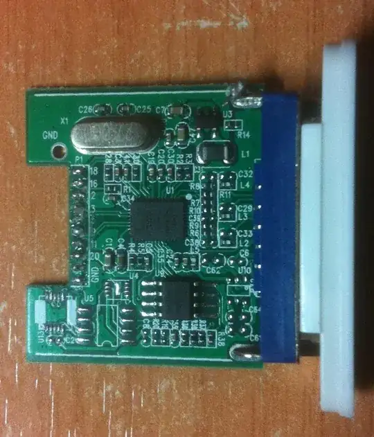
Here's a picture showing chip information on the board. As mentioned on the comments, my bet is that this is a standard DisplayPort to VGA conversor board. But I haven't found any info on it.
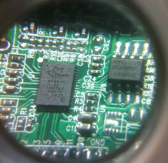
Text on chips:
Big chip (Parade):
PSB617
A0
UOBCAC
0807H
C 1420
SmallerChip (BergMicro):
25Q40ASTCG
1406
Update 2
The Parade chip/board is described here: www.paradetech.com/products/displayport-format-converters/ps8617/ (not enough rep to post more links).
I believe the first question to answer is the cable color correspondence of the ThunderBolt end, I don't know if there's a standard, or if that's possible without tearing the wire apart.