OpenSCAD User Manual/FAQ
General
How is OpenSCAD pronounced?
The intended pronunciation is: Oh - Pen - Ess - CAD
What is the meaning of the S in OpenSCAD?
The S stands for Solid as Solid modeling.
Why Is There No Preview on Windows in a Virtual Machine?
It is likely that your VM or session does not support the required version of OpenCSG/OpenGL for correct preview rendering.
Note: Also applies when working via Remote desktop using RDP (Windows) or XfreeRDP (Linux )
A solution is to use software rendering via the Mesa driver from the MSYS2 package.
Download the Repo for the version appropriate to your Windows installation:
64bit - mingw64 Repo at https://packages.msys2.org/package/mingw-w64-x86_64-mesa?repo=mingw6432bit - mingw32 Repo at https://packages.msys2.org/package/mingw-w64-i686-mesa?repo=mingw32
[Deprecated: Support for 32 bit applications is deprecated after Windows 10 and will be removedin a future release. Use 64 bit programs instead]
An decompression app like 7-zip or WinRAR will be needed to extract the contents of the *pkg.tar.xz file.
Find the file mingw64\bin\opengl32.dll in the extracted folder.
Note that even in a 64 bit system the name of the .dll still has "32" in it.
Copy opengl32.dll to the OpenSCAD installation directory, which is normally c:\program files [for 64bits] or c:\program files(x86) [for 32bits].
Restart OpenSCAD and preview should function normally.
Display
What is the Convexity Parameter ?
This is now documented in a new page on Rendering Isssues.
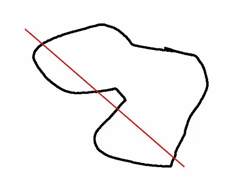
This image shows a 2D shape with a convexity of 2, as the ray indicated in red intersects with the 2D shape in at most two sections. The convexity of a 3D shape would be determined in a similar way. Setting it to 10 should work fine for most cases.
The term comes from the OpenCSG rendering package
Why Isn't Preview Working?

Some systems, in particular Intel GPUs on Windows, tend to have old or broken OpenGL drivers. This affects preview rendering when using difference or intersection operators.
The following tends to improve the situation: Edit->Preferences->Advanced->Force Goldfeather (see screenshot).
What are those strange flickering artifacts in the preview?

This is typically caused by differencing objects that share one or more faces, e.g.:
cube_size = 20;
difference() {
  cube(cube_size, center = true);
  cylinder(r = 10, h = cube_size, center = true);
}
In some cases the final render works fine, but designs with coincident resulting faces should be considered a design with undefined behavior, as a proper render result is not guaranteed. The fundamental source of the issue is not a bug, but an intrinsic property of the inability to rigorously compare floating point values which might have undergone trigonometric operations (like rotations) resulting in irrational values that simply cannot be represented exactly in any manner. Because of this you can get near-coincident surfaces where part of the surface is inside and part of the surface is outside, or zero-volume regions, resulting in a render error that the output is not manifold. In simple tests like this example, the render will typically be okay giving false confidence in this approach, but if both pieces were subject to an equal rotation it can fail to render in a manner which is slightly dependent on the platform the program is running on. This will typically result in a warning at render, and a rendered piece being removed from the final output.
The solution to this is to always provide a clear overlap for surfaces which are to be removed, such as by adding a small value called an epsilon:
cube_size = 20;
difference() {
  cube(cube_size, center = true);
  cylinder(r = 10, h = cube_size+0.01, center = true);
}
Note that a similar issue occurs with unions, where coincident faces to be merged must also be given an epsilon value to guarantee they are always inside.
There is a second preview-only flickering result which can also occur with faces that are not even supposed to be visible in the final result, for example because they're were negative faces used for removal by a difference() operation. This second case impact of fully properly removed faces (or negative faces) is an artifact of the library used for drawing the preview, and will not affect the render. If a clean preview result is desired such as for imaging output, these can be adjusted by an epsilon value in the same manner.
See this discussion for other details.
Why are some parts (e.g. holes) of the model not rendered correctly?

This can happen when using features like linear_extrude() or when importing objects. The convexity of the objects is not known. For more complex objects, the convexity parameter can be used to specify the value. Note that higher values cause a slowdown in preview.
difference() {
    linear_extrude(height = 15 /* , convexity = 2 */) {
        difference() {
            square([50, 50]);
            translate([10, 10]) circle(5);
        }
    }
    translate([25, 25]) cube([5, 5, 40], center = true);
}
The user manual (section Extrude parameters for all extrusion modes) describes how to calculate the number that should be given to the convexity parameter.
And other workaround might be to use render() to forces the generation of a mesh even in preview mode.
Why does difference (or intersection) sometimes not work in preview?


difference() {
    sphere(10);
    cube(100);
}
In perspective mode, the previewer does not process differences or intersections where the camera is inside the invisible object. This is most commonly seen when using a large object to cut away significant parts of the model.
Workarounds:
- Keep the camera outside the invisible objects.
- Keep the invisible objects modest-sized so that it is easier to keep the camera outside them.
- Wrap render() around the difference or intersection.
- Use orthogonal mode.
Why is my model appearing with F5 but not F6?

This can be caused by polyhedrons with flipped faces.
This can be visualized in "Thrown Together" display mode. See misordered faces for details.
points = [[5,5,0],[5,-5,0],[-5,-5,0],[-5,5,0],[0,0,3]];
faces = [[0,1,4],[1,2,4],[2,3,4],[3,4,0],[1,0,3],[2,1,3]];
polyhedron(points, faces);
If the model imports external STL files, see also import related question. It is confusing that the error only occurs if there is more than one object involved, ie it "works" until you add another item.
Why is the preview so slow?
Intersections or difference operations that use objects to cut holes, chamfer, or generally remove part of a solid are expensive. The preview rendering expects to have only primitive objects used as negatives so anything more complex has to be unpacked.
For example (using A+B = union() / A-B = difference() / A*B = intersection()):
A - B*C - D*E
becomes: A-B-D + A-B-E + A-C-D + A-C-E
..and if A is more complex:
A+B - C*D - E*F
becomes: A-C-E + A-C-F + A-D-E + A-D-F + B-C-E + B-C-F + B-D-E + B-D-F
All combinations have to be rendered, which can take some time, especially on older GPUs, and especially on low-end Intel GPUs.
Import
How can I Clean Up STL Issues ?
To work well the meshes in an STL file should be be manifold, not contain holes, nor intersect itself. Even with such issues the import process may well succeed and show something in the preview panel. However, operating on that object, or doing a full render, will likely
- emit warnings about it not being manifold
- cause it to disappear
- to emit CGAL errors like:
 CGAL error in CGAL_Build_PolySet: CGAL ERROR: assertion violation!
 Expr: check_protocoll == 0
 File: /user/openscad_deps/../CGAL/Polyhedron_incremental_builder_3.h
or
 CGAL error in CGAL_Nef_polyhedron3(): CGAL ERROR: assertion violation!
 Expr: pe_prev->is_border() || !internal::Plane_constructor<Plane>::get_plane(pe_prev->facet(),pe_prev->facet()->plane()).is_degenerate()
There are several ways to clean an STL file:
- MeshLab
- This free software can fix all issues.
Using MeshLab, you can do:
- Render > Show non Manif Edges
- Render > Show non Manif Vertices
If bad edges or verticies are found, use menu:
Filters > Selection > Select non Manifold Edges
or
Filters > Selection > Select non Manifold Vertices
and then Apply and Close.
IF there are bad items a button, "Delete the current set of selected vertices..." should be used to remove them.
Otherwise the screen will show "0 non manifold edges" and "0 non manifold vertices"
There is a useful explanation on YouTube in the Meshlab Channel.
Now all of the holes you made have to be filled back in. Select a hole, click Fill, and then Accept, and repeat until the mesh is correct.
Use menu File > Export Mesh to export to STL.
Using Blender is a possible alternative to Meshlab:
- Start Blender
- 'X, 1' to remove the default object
- File > Import > STL
- 'Tab' to edit the mesh
- 'A' to de-select all vertices
- 'Alt+Ctrl+Shift+M' to select all non-manifold vertices
- 'MMB' to rotate, 'Shift+MMB' to pan, 'wheel' to zoom
- 'C' for "circle" select, 'Esc' to finish
- 'Alt+M, 1' to merge or 'Space' and search for "merge" as alternative
This instruction is showing the Key stroke shortcuts ('X' etc) to Blender operations and MMB is Middle Mouse Button.
Merging vertices is a useful way of filling holes where the vertices are so closely packed that the slight change in geometry is unimportant compared to the precision of a typical 3D printer
Why is my imported STL file appearing with F5 but not F6?
This is mostly caused by bad geometry in the STL file. Use an app like Blender, MeshLab, NetFabb, or Prusa Slicer to import, repair and re-export the clean version. In essence the model needs to be manifold to be processed in OpenSCAD.
Even a bad model may appear in preview mode as there is no real geometry yet. The preview actually painting pixels based on a view of the model.
A specific issue are the so called "Zero faces" where the 3 points of a triangle are co-linear, which is currently not handled well in OpenSCAD.
Using MeshLab
MeshLab has a filter to remove zero faces by flipping edges of polygons
Filters -> Cleaning and Repairing -> Remove T-Vertices by Edge-Flip
Set the Ratio to a high value (e.g. 1000000), otherwise it's possible the model gets distorted.
Using Blender
Blender has a 3D-Printing-Toolbox Plug-in (needs to be enabled in the UserSettings) that can show issues with the STL file. See http://wiki.blender.org/index.php/Extensions:2.6/Py/Scripts/Modeling/PrintToolbox
Prusa Slicer
In the menu File > Repair STL will take a file and make it acceptable to Slicer, if it can.
What are "Unsupported DXF Entity" warnings?
Warning messages like Unsupported DXF Entity 'SPLINE' (1c1) in "file.dxf" mean that the DXF file was written using features that the our import processor does not support.
The importer will still import the parts it can, but your model may be incomplete .
Can I Use Inkscape to Make 2D Drawings ?
When using Inkscape to draw a design it is good practice to convert all Bezier curves to short line segments using
Extensions > Modify Path > Flatten Beziers ...
which pops up a dialog with a setting for the max length of the line segments to use. Shorter lines, thus more lines, produce smoother results at the cost of more processing and data. When exporting select format "AutoCAD DXF R14".
Exporting to SVG or DXF will work with the import() module to bring your drawing into OpenSCAD.
A more detailed tutorial is available at RepRap.
Can I Import Inkscape 2D Models to OpenSCAD ?
Inkscape is an open source drawing program. Tutorials for transferring 2d DXF drawings from Inkscape to OpenSCAD are available here:
- Simple drawing using only straight line path segments on RepRap
- A complicated process for using text in OpenSCAD using conversion to Postscript. Obsolete since version 2021.01 added the
text()module. - Extension for DXF Export w native support of Beziers
- Convert any 2D image to a 3D object using OpenSCAD on Instructables
- directly exports OpenSCAD file (French) Note: The original FabLab site is being renovated. This should be a link to the same page, now located in the cyberweb.cite-sciences-fr site
Export
How can I export multiple parts from one script?
Answer based on comments in related issue on github https://github.com/openscad/openscad/pull/1534#issuecomment-227024209
There is a way to generate a bunch of geometric primitives and export them as STL files from a single script, without commenting/uncommenting code.
The variable PARTNO indicates which part is being exported in the current run. If PARTNO is 'undef', then nothing is exported.

 PARTNO = undef; // default part number

 module tree() {
   color("green") cylinder(r1 = 12, r2 = 1, h = 30);
   // ...
 }

 module trunk() {
   color("brown") cylinder(r = 3, h = 10);
   // ...
 }

 module base() {
   color("white") translate([-10, -10, 0]) cube([20, 20, 5]);
   // ...
 }

 if (PARTNO == 1) tree();
 if (PARTNO == 2) trunk();
 if (PARTNO == 3) base();

 // optionally use 0 for whole object
 if (PARTNO == 0) {
   base();
   translate([0, 0, 5]) trunk();
   translate([0, 0, 15]) tree();
 }
When working interactively, the PARTNO variable at the top of the file can be set to the number of the part to be shown/exported from the GUI.
It's possible to automate the process of exporting all of the parts by writing a shell script on MacOS or Linux, or a batch file on Windows. The shell script would look something like this:
 # export parts as STL
 openscad -DPARTNO=1 -o tree.stl model.scad
 openscad -DPARTNO=2 -o trunk.stl model.scad
 openscad -DPARTNO=3 -o base.stl model.scad

 # export image of all the parts combined
 openscad -DPARTNO=0 -o model.png model.scad
Running this script once from the command line exports all of the parts to separate files.
How can I export screenshots with higher resolution than the current window
Right now that is not possible from the GUI, as the images are restricted to the actual display context. Using the File->Export->Export As Image menu always exports at viewport resolution.
It is however possible to generate higher resolution images via command line using the --imgsize parameter. This uses a separate drawing context, size-limited by memory and the graphics driver, to generate the image. For example, on Linux, the Mesa driver for Intel UHD Graphics 620 (Kabylake GT2) seems to max out at an image resolution of about 16000×16000.
 $ openscad --imgsize 16000,16000 -o CSG.png CSG.scad
 ECHO: version = [2019, 1, 0]
 Compiling design (CSG Products normalization)...
 Normalized CSG tree has 6 elements
 $ file CSG.png
 CSG.png: PNG image data, 16000 x 16000, 8-bit/color RGB, non-interlaced
Language
Why am I getting an error when writing a = a + 1?
The short answer is that in this language a variable may not appear on both sides of an assignment statement.
When we add in the effect of block and FoC statements opening local scopes it is possible that an assignment may look like it is breaking this rule. But reusing a variable name, like "x", inside a block is defining a new, local variable so using the "x" from outside the block on the RHS of the "=" sign is correct and allowed.
x=12;
if(true) {
  x=x+1;   // local = global + 1
  echo(x); // ECHO: 13
  }
echo(x); //ECHO: 12
The deeper answer is based on this language being a declarative functional language. In a functional language a script is list of instructions (statements) that are compiled into a run-able form using a script's initial conditions as the basis for every calculation, decision, and loop carried out in strict order. Statements in the script are only ever visited once and every variable that receives the value of a calculation can only be set once, effectively making it a constant. Decisions, If-Then-Else statements, are made with the values extant when their statement is compiled and only the statements on the branch selected make it to the run-able code. Loops are unrolled so the body of the loop is copied as many times as the loop should run, and in each copy the loop control values are set as "constants" of the updated value by the compilation process.
How can i fake iteration without a = a + 1 ?
The standard tactic to process a list, or an array of data, or even to repeat an action is to iterate. But in a function language the activity of updating a loop counter is not available.
However, there are some useful alternative ways to process data in a Functional Language:
- Precalculate a list
- use one of the list comprehension tools.
- looping
- create a new value of the variable for each step in the loop.
- Use recursion
- iterative processing of values by using a function or module to process just one, then call itself to handle the rest of the data.
Examples
Return the sum of the values in a vector:
function sum_vec(vec, from = 0, to = undef ) =
   let( end = is_undef( to ) ? len(vec)-1 : to )
   ( from == end ? vec[end] : vec[end] + sum_vec(vec, from, end-1 ) );
Cumulative sum of values in vector valid
function cumsum_vec(v) =
   let( lenv = len(v) )
   [for(a = v[0], i = 1; i < lenv;
        a = a+v[i], i = i+1) if(i==lenv-1) a+v[i]
   ][0];
Notice that the return from the function is only the 0-ht element, the only element that is actually added to the vector.
Return true when any of the elements of the given vector are true. The elements of the vector will be evaluated as boolean values according to the rules for the different types of the language.
function any(booleans, index=0) =
   vec_is_empty( booleans) ?
       undef
   : index > len(booleans)?
       false
   : booleans[index]? true :
       any(booleans, index+1)
   ;
A purely recursive solution for canvasing all the elements of a list.
The return of undef is used to signal bad input.
Set all letters in a strong to "lower case". This is the interface function that does all of the input checking
function lower(string) =
   is_not_string( string ) ?
       undef
   : str_is_empty( string ) ?
       ""
   : str_lower( string )
   ;
This is the processing function
function str_lower(string) =
   chr( [for (c = string)
           _is_in_set( c, _STRING_UPPER ) ? ord(c)+_ASCII_CONVERT : ord(c)
       ])
   ;
This is taking advantage of the chr()'s ability to implicitly convert an vector of single character elements into a string.
Note that _is_in_set() is a self made function that does what it says.
Are measures being considered to help procedural programmers ?
The view that "variables may not be changed" is a limitation can hopefully be changed by showing how to better exploit the opportunities.
- A "reduce" function
- to help with collecting information depending on a list of input. I have created the page and linked to the Wikipedia on the issue
- Recursion is fine
- we already detect and handle Tail-End Recursion now, but additional help features are possible
- Disallow Reassignment
- The editor could be enhanced to fail with an error when x=x+1 is detected. Note: That used to be true. In dev snap releases x=2; if(true) { x=x+1;} is adding the global 'x' to the local 'x' and is legal
- Command-Line Variable Override
- a new syntax or other mechanism for achieving this would be part of implementing Disallow Reassignment. Note: but doing so could break shell scripts that folks use to automate rendering etc on the command line
Aspects of the Zen of Functional Language Processing
- Imagine that all the expressions in a script are executed in parallel. Any dependency of one expression on another must be made explicit by hierarchical grouping. This view makes iterating to accumulating information unnecessary.
- OpenSCAD functions operate the way that a spreadsheet cell does. A spreadsheet formula cannot increment itself as that would be circular reference.
It might be possible to create features to help programmers apply their procedural programming skills in OpenSCAD. But the team is working in alignment with the technology .
Learning something from plethora of HTML generators out there all trying to create web pages we note that they are used to make a script that make snapshot "images" every time a web page is refreshed. In this vein there are OpenSCAD "generators" in other programming languages (python, ruby, C++, haskell, clojure are known) just as there are tools offering Javascript interfaces for similar purposes (OpenJSCAD, CoffeeSCAD).
However until the need for such a solution becomes overwhelming, and a good candidate for the language to use, it's better to keep these things separate.
See also for help: List Comprehension, Tips & Tricks, Recursive Functions
User Interface
OpenSCAD isn't adhering to my GTK desktop theme
You may need to install package "qt5-style-plugins" on Debian-based systems and "qt5-qtstyleplugins" on Fedora-based systems, then set environment variable when calling openscad QT_QPA_PLATFORMTHEME=gtk2 openscad
To make the setting permanent, add export QT_QPA_PLATFORMTHEME=gtk2 to your user's ~/.profile
OpenSCAD GUI is not scaled in Gnome on a 4K / HIDPI Monitor
The GUI Framework Qt used by OpenSCAD seems to need an extra hint to automatically scale correctly for 4K / HIDPI Monitors on Gnome/X11 (e.g. reported on Ubuntu 22.10 with fractional scaling set to 125%).
- Copy
openscad.desktopfrom/usr/share/applications/to~/.local/share/applications - Change
Exec=openscadtoExec=env QT_AUTO_SCREEN_SCALE_FACTOR=1 openscad
I'm not getting any menubar when running OpenSCAD in Ubuntu, how can I get it back?
This seems to be caused by Ubuntu messing with Qt to move the menubar somewhere else (e.g. top of the screen).
That problem hits other applications too, see https://bugs.launchpad.net/ubuntu/+source/appmenu-qt5/+bug/1307619
There are two things that could help:
- Set the
QT_QPA_PLATFORMTHEMEenvironment variable to an empty string (the default value is probably "appmenu-qt5") or simply run OpenSCAD withQT_QPA_PLATFORMTHEME= openscad - Remove the
appmenu-qt5package to globally disable menubar changes for all applications
Why are the error line numbers wrong?
That is a limitation/bug in the current parser that handles include<> basically as copy&paste of content. In some cases it's possible to work around the issue by placing the include<> statements at the end of the file.
When depending on libraries, it's recommended to use use<> instead which does not have that problem and also automatically inhibits any top-level geometry of that file (which might be there as demo for the library).
I don't like the editor, can I use my favourite editor instead?
Yes, OpenSCAD supports a special mode that reloads the files if they are modified externally. To enable this mode, check the Design -> Automatic Reload and Preview option and just close the editor window (or use View -> Hide Editor).
See also the section in the user manual: Using an external Editor with OpenSCAD
As an example, here's a script that runs vim as editor and also starts OpenSCAD, which takes the model viewer role.
It supports 3 modes
- Run with no parameters, it opens a temp file for quick testing, which it deletes.
- Run with the name of a non-existent file, it starts the file with a default license header.
- Run with the name of an existing file, it simply opens it.
#!/bin/bash

FILE="$1"
AUTHOR="Your Name Here"
YEAR="$(date "+%Y")"
LICENSE="// Created in $YEAR by $AUTHOR.\n// This work is released with CC0 into the public domain.\n// https://creativecommons.org/publicdomain/zero/1.0/"

# increase stack size to allow deeper recursion
ulimit -s 65536

if [ "$FILE" == "" ]
then
  TEMPF=`mktemp --suffix=.scad`
  openscad "$TEMPF" >/dev/null 2>/dev/null &
  vim "$TEMPF"
  rm -f "$TEMPF"
  exit
fi

if [ ! -e "$FILE" ]
then
  echo -e "$LICENSE" >> "$FILE"
fi

openscad "$FILE" >/dev/null 2>/dev/null &
vim "$FILE"
Errors / Problems
Why am I getting "no top level geometry to render"?
This can have different reasons, some common ones include
- Missing / Commented out module call
module model() {
  cube(20);
}
%model();
Using the % modifier does not only make the part transparent, it also causes the part to be excluded in the final render!
- Difference / Intersection with wrong translated objects
The easiest way to solve this type of issues is to highlight the objects using the # modifier and see if the objects are placed at the position where they should be.
- Importing broken STL files
See Why is my imported STL file appearing with F5 but not F6?
OpenSCAD crashed/was killed, are my unsaved changes lost?
Before starting a preview or render a backup file is made of the current .scad file. It is saved in the user's Documents folder in an "OpenSCAD" folder
ON Windows 11 : "C:\Users\xxxx\Documents\OpenSCAD\backups"
ON Linux : $HOME/.local/share/OpenSCAD/backups
The path can be seen in the app in the pop-up window shown by menu item Help > Library Info dialog titled "Backup Path".
OpenSCAD crashes when clicking "New" or loading a file on Windows
OpenSCAD crashes on some machines with Intel graphics drivers, for more details, see https://github.com/openscad/openscad/issues/2442
OpenSCAD fails to run due to missing DLLs
This is an issue with the special Windows N (Europe) and KN (Korea) versions from which the Windows Media Framework was removed by a ruling against anti-competitive practices by the European Commission in 2004.
The missing files are EVR.dll, MF.dll, or MFPlat.dll
OpenSCAD, starting with release 2019.05, depends on some of the features so it fails to run on those systems.
The missing Windows Media Framework can be added by installing the correct "Media Feature Pack for N versions" from the list Microsoft provides in KB3145500. For Windows 10 version N, there's a dedicated download page with Windows version selector at: https://www.microsoft.com/en-us/software-download/mediafeaturepack.
Starting with Windows 10 1909 you can't download the Media Features from the Microsoft Website directly - instead you have to use Windows Settings > Apps > Apps and Features > Optional Features > Add a Feature and find the Media Feature Pack in the list of available Optional Features. Afterwards reboot and it should work.
Reporting bugs, Requesting features
How do I report bugs?
Bugs in OpenSCAD are best reported in the github issue tracking system at . If you are not sure it's a bug ask about it in the IRC chat.
Please search existing issues if the bug was already reported. If you find something similar but are unsure of its relevance, create a new issue and mention the (possibly) related one.
Make your report as complete as possible so that we can reproduce it and understand the cause. These are info items we like to see :
- The OpenSCAD version
- Menu Help > About and Help > Library Info or
Command line: openscad --info - The Operating System name and version
ON Windows : Settings > System > About : sections Device and Windows
- Describe your workflow that led to the problem
- graphics issues
- the OpenGL driver information
- your script (if relevant)
- if short paste it in, otherwise a link to it on something like pastbin is better.
How do I request new features?
New features or changes/extensions to existing features can be requested in the github issue tracking system at https://github.com/openscad/openscad/issues too.
Please make an effort to clearly explain the new feature / change as detailed as possible. Including some background about why you think this feature would be useful to you and other people helps a lot and increases the chances of it being implemented.
Best Way to Report OS Specific Bugs ?
The versions for Windows and Mac OS X are currently maintained by the OpenSCAD team, so please use the GitHub issue tracker to report issues.
The nightly builds hosted on the openSUSE build service are also maintained by the OpenSCAD team, so please use the github issue tracker for reporting issues with them.
The OpenSCAD versions in the various Linux distributions are usually maintained by them. Bugs specific to an OS should be reported in their respective systems:
- Debian
- See "please report it" directions
- Ubuntu
- See "Report a bug" directions
- Fedora / Red Hat
- See the current list and use this page to report.
- Arch Linux
- See "reporting bug guidelines" directions