OpenSCAD User Manual/The OpenSCAD User Interface
Graphic User Interface
The OpenSCAD GUI is a flexible tool for interactively editing a script with instant feedback in the rendered preview, and supporting information from the console, error log and other information panels.
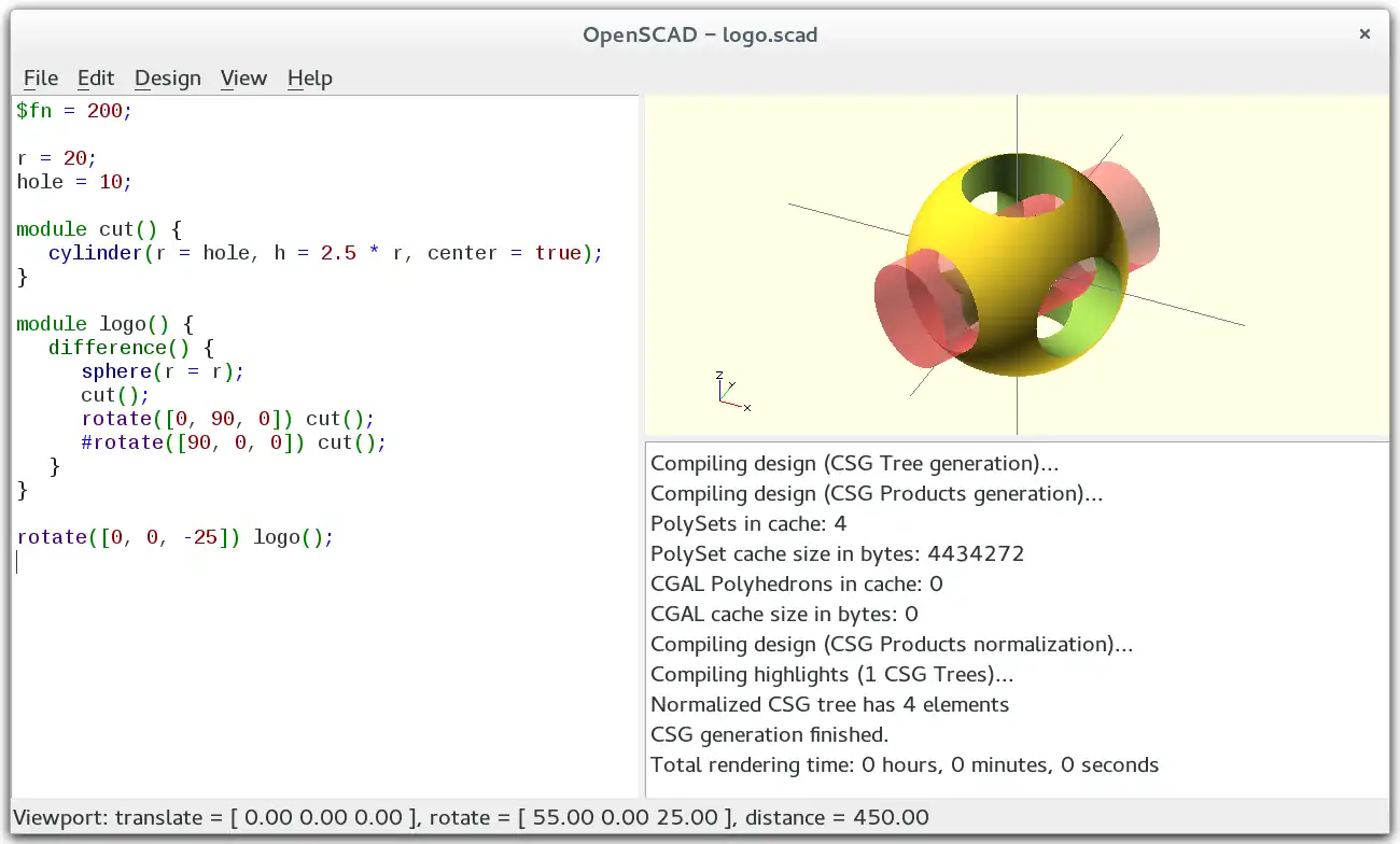

By default the application window shows three panels:
- Editing Panel
- Console
- Preview
Text Editor
The Scintilla based editor offers all of the features that a modern programmers tool should offer:
- multiple files open on tabs
- search & replace
- syntax highlighting
- keyword and argument list completion
- interactive value change
- indenting
- apply and remove comments
Interactive Modification of A Number
It is possible to change a numeric value in the source code and observe the result in real time.
Place the cursor after a numeric digit and, while holding the Alt key, use the up arrow to increment the digit and down arrow to decrement it. The Preview is re-rendered after every change. Alt + Right Arrow or + Left Arrow move the cursor to the next less significant and next more significant digit respectively. In addition, when the cursor is at the least significant digit, the Alt + Right Arrow will add a decimal point and the first digit of the fractional component, and more significant digits thereafter.
ON MacOS : use ⌥ Option+⇧ Shift instead of + Alt
| Key Combo | Description |
|---|---|
| Alt + Up Arrow | Increment the numeric value to the left of the cursor. |
| Alt + Down Arrow | Decrement the numeric value to the left of the cursor. |
| Alt + Left Arrow | Move the cursor left to the next most significant digit. |
| Alt + Right Arrow | Move the cursor right to the next less significant digit, and possibly a fraction. |

Console
Shows information from the operation of the app, normally just the results of compiling or rendering a program. Compilation may emit warnings, errors and assertion faults, as well as messages emitted by Echo() statements in the program.
During a full (F6) rendering a progress-bar is displayed in the bottom frame border of the console, with a Cancel button that can interrupt it.

Preview
The Preview rendering is updated automatically after any change to the script or the Customizer data.
There are a number of options on the View menu that enable objects in the Preview, like Show Axes to display coloured pointers for the 3 Coordinate Axes. The View menu shows the keyboard shortcuts for each option.
The viewing area is navigated primarily using the mouse:
| Action | Icons | Description |
|---|---|---|
| rotating the view | Dragging with the left mouse button rotates the view along the axes of the viewing area. It preserves the vertical axis' direction.
Double-click the left button to set the point of rotation. | |
| ⇧ Shift + |
Dragging with the left mouse button when the shift key is pressed rotates the view along the vertical axis and the axis pointing towards the user. | |
| moving the viewing area | Dragging with the right mouse button moves the viewing area. | |
| zooming | Using the scroll wheel | |
| Dragging with the middle mouse button | ||
| ⇧ Shift + |
Dragging with the right or middle mouse button and the shift key pressed | |
| ⇧ Shift + | ||
| + and - | The keys + and - (Ctrl+[ and Ctrl+]) | |
| show/hide rotation center | Ctrl+3 | Turn on or off the graphic showing the center of rotation. (It is always in the center of the viewing area). |
| rotation reset | Ctrl+0 | Rotation can be reset using the shortcut Ctrl+0. |
| translation reset | Ctrl + ⇧ Shift+0 |
Translation can be reset using the shortcut Ctrl+⇧ Shift+0. |
Manifold Render Mode
[Note: Requires version Dev Snapshot]
This method gives fast rendering with few if any, rendering artifacts from convoluted geometry.
Note: must be enabled in Preferences>Advanced>Backend dropdown
Note: This rendering engine ignores the convexity parameter
OpenCSG Render Mode (F9)
[Note: Requires version pre-Snapshot versions]
This method gives fast rendering for preview, but slows significantly when working with convoluted objects.
Selecting the OpenCSG mode using F9 switches to the last generated OpenCSG view, but does not re-run the source code. If Automatic-Reload and Preview is not enabled the Design-Compile (F5) function triggers the evaluation of the source code torefresh the Preview.
CGAL Tesselate and Render
[Note: Requires version pre-Snapshot versions] This method of rendering was triggered using menu items to tessellate and render the model (keys F10 and F11 respectively). These keybindings are removed in recent versions.
CGAL is the Computational Geometry Algorithms Library, an open source tool set that includes tessellation and rendering functions. When invoked it first builds a polygonal mesh from the model, then renders it. Using this library can be slower for single images but is a significant advantage when rendering multiple images for an animation. It also produces a more accurate rendering of the surfaces in the model than the OpenCSG version.
As with OpenCSG preview, F10 and F11 only enable the full render mode and don't run the program to update the model; for that, the Design-Compile and Render (F6) menu item should be used.
It is possible to combine the benefits of these two display methods using the render() Operation Module. It generates the mesh that is used as the basis for rendering, even with OpenCSG mode enabled.
View options
Show Edges (Ctrl+1)
When Show Edges is enabled, both engines render edges as well as faces. In addition, the CGAL rendering includes the vertices.
Limitation: This option has no effect when CGAL grid mode is active

OpenCSG rendering does not consider edges created by boolean operations in a model, while the CGAL tessellation process does.
Show Axes (Ctrl+2)
When Show Axes is enabled an orthogonal axes indicator is displayed at the origin. Additionally, a smaller axes indicator is shown in the lower left corner of the viewing area. This three lines in this indicator are titled X, Y, and Z and are coloured red, green, blue respectively.
Show Crosshairs (Ctrl+3)
When Show Crosshairs is enabled, the center of the viewport is indicated by four lines pointing in the diagonal directions of the global coordinate system. This is useful when aligning the viewing area to a particular point in the model to keep it centered on screen during rotation.
Animation
The menu item Window-Animate enables the processing of an animation sequence, updating the model at each step, and optionally rendering images.
An animation panel is added to the window, normally attached to the lower border in the central panel space. The panel has fields for the time value ($t), Frames Per Second (FPS) and Steps and controls for stopping and starting its operation, which starts Paused when the panel is opened.
As soon as FPS and Steps are set, animation begins, which can be seen as the Time increases.
The animation period runs from zero to 1, divided into Steps at which the model will be evaluated and rendered. The FPS setting determines how many times per second frames should be rendered.
Reasonable starting values are FPS=10 and Steps=100.
The operation of an animation is controlled by Special Variable $t.
View Alignment
The default view is looking at the origin along the vector [-45,-35,-65] (degrees) from a distance of approximately 150 units.
Use the menu item View > Reset View to return to this view point.
The View menu items Top, Bottom, etc.; center the view looking at the origin along their respective axis. The "O" character in the view icons along the bottom of the viewport indicate the Observer position as 'hints' as to the function of their buttons.
The View > Diagonal option changes the direction of view back to the default vector, but does not change the view point.
The View > Center option centers the global coordinate origin in the view without changing the direction of view.
The View > View All option zooms the view out so that all shapes are in view, without changing the direction of view nor centering it.
The shapes in the view can be shown in either Perspective or Orthogonal mode. In Orthogonal mode the different views, Top, Left etc., show the model in the Top-Side-Front views of an engineering drawing.

Default View Example
%cube(10, center=true);

rotate([-45,-45,-45]){
    translate([30,0,0])
    color("lightgreen")cube(5, center=true);
    translate([100,0,0])
    color("green")cube(5, center=true);
    }

rotate([-45,-35,-65]){
    translate([30,0,0])
    color( "pink" ) cube(5, center=true);
    translate([100,0,0])
    color( "red" ) cube(2, center=true);
    }