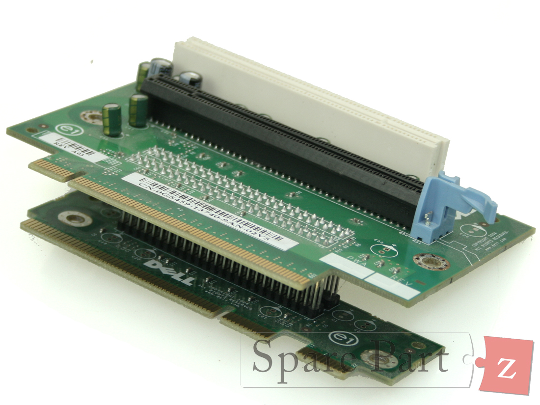
This is a picture of the board out of a Dell Optiplex 980, the board's part number being D441T: link to image
The board clearly has two PCIe x16 slots (though one is wired with just four lanes, apparently), one PCIe x1 slot in the front (for a wireless card), and two PCI slots.
But that's where it gets a bit strange for me. I can easily recognize the smaller of the two PCI slots as a very standard 5V, 32-bit PCI slot, but the other one has me stumped. It's clearly not a 64-bit slot, since the third segment is way too small. I've also heard of "PCI Professional" and while images of "PCI-P" slots are hard to find they also seem to look different.
Was this some sort of Dell-proprietary PCI extension for a multi-slot riser card (mentioned in the Optiplex 980 manual) in order to supply more address lines? PCI is shared-bus so I'm not sure why they'd need such a thing, but the era this board is from was no stranger to bizarre proprietary hardware...
Any insight would be appreciated!
This question has been mentioned a couple times as a possible duplicate, but it doesn't appear that is the case. Despite being about a similar board, that question is asking about the difference between PCI and PCIe. This question is about the difference between two specific PCI slots.
One of the comments included this useful link to an image showing the various PCI keying patterns. Note that the longer PCI slot on the board doesn't match any of the keying patterns in that image. The closest is the "5V 64-bit PCI Card" pattern, but the difference there is that the second small slot segment on the board is the same size as the first small slot segment. Long-small-small, rather than long-small-medium, basically.

