OpenSCAD User Manual/2D Primitives
All 2D primitives can be transformed with 3D transformations. They are usually used as part of a 3D extrusion. Although they are infinitely thin, they are rendered with a 1-unit thickness.
Note: Trying to subtract with difference() from 3D object will lead to unexpected results in final rendering.
Square Object Module
By default this module draws a unit square in the first quadrant, (+X,+Y), starting at the origin [0,0]. Its four lines have no thickness but the shape is drawn as a 1 unit high, filled plane.
The module's arguments may be written in the order <size>, center=<bool> without being named, but the names may be used as shown in the examples:
Parameters
- size
- has two forms: single value or vector
- single - non-negative float, length of all four sides
- array[x,y] of two non-negative floats, the length of the sides in the x and y directions
- center
- boolean, default false, to set the shape's position in the X-Y plane
Center
When false, as it is by default, the shape will be drawn from its first point at (0,0) in the First Quadrant, (+X,+Y).
With center set to true the shape is drawn centered on the origin.
Examples
Except for being 10 cm square this is a default square:
 square(size = 10, center=false);
 square(10,false);
 square([10,10]);

And to draw a 20x10 rectangle, centered on the origin, like this:
 square([20,10],true);
 a=[20,10]; square(a,true);

Circle Object Module
By default this module draws a unit circle centered on the origin [0,0] as a pentagon with its starting point on the X-axis at X=1. Its lines have no thickness but the shape is drawn as a 1 unit high, filled plane.
The circle() shape is drawn as if inscribed in a circle of the given radius, starting at a point on the positive x axis.
The argument radius may be given without being named, but the r and d arguments must be named.
Parameters
- 1) radius
- non-negative float, radius of the circle
- r
- non-negative float, radius of the circle
- d
- non-negative float, diameter of the circle
- $fa
- Special Variable
- $fs
- Special Variable
- $fn
- Special Variable
The default circle displays as a pentagram as that is the minimum number of fragments used to approximate a curved shape calculated from the default values for $fs and $fa. To have it draw as a smooth shape increase the $fn value, the minimum number of fragments to draw, to 20 or more (best $fn < 128).
An alternative method to draw a very smooth circle scale is to scale down a very large circle.
scale( 0.001 ) circle(200);

Equivalent scripts for this example
 circle(10);
 circle(r=10);
 circle(d=20);
Drawing an Ellipse
There is no built-in module that for generating an ellipse, but the scale() or resize() operator modules may be used to form an ellipse.
See OpenSCAD User Manual/Transformations
Examples
resize([30,10]) circle(d=20); // change the circle to X and Y sizes

scale([1.5,0.5]) circle(d=20); // apply X and Y factors to circle dimensions

Regular Polygons
There is no built-in module for generating regular polygons.
It is possible to use the special variable $fn rendering parameter to set the number of sides to use when drawing the circle().
circle(r=1, $fn=4); // generate a unit square
Examples
The following script draws these these examples:

translate([-42,  0])
    {circle(20,$fn=3);  %circle(20,$fn=90); }
translate([  0,  0]) circle(20,$fn=4);
translate([ 42,  0]) circle(20,$fn=5);
translate([-42,-42]) circle(20,$fn=6);
translate([  0,-42]) circle(20,$fn=8);
translate([ 42,-42]) circle(20,$fn=12);

color("black"){
    translate([-42,  0,1])text( "3",7);
    translate([  0,  0,1])text( "4",7);
    translate([ 42,  0,1])text( "5",7);
    translate([-42,-42,1])text( "6",7);
    translate([  0,-42,1])text( "8",7);
    translate([ 42,-42,1])text("12",7);
    }
Another way to solve the lack of a built-in module for regular polygons is to write a custom one: module regular_polygon()
Polygon Object Module
The polygon() module draws lines between the points given in a vector of [x,y] coordinates using, optionally, one or more "paths" that specify the order of the points to draw lines between, overriding the "natural" order. Polygons are always created in the X-Y plane and are co-planar by definition.
A polygon is the most general of the 2D objects in that it may be used to generate shapes with both concave and convex edges, have interior holes, and effectively perform boolean operations between shapes defined by paths.
Note that the order of the points sets how the lines will be drawn so complex shapes made with crossing lines can be achieved without using a path argument, but making interior holes do require the use of at least two paths to set the interior and exterior boundary lines.
The determination of which parts of the polygon to fill and to leave empty is handled automatically and it is only the filled parts that will be extruded, if the shape will be used as a basis for that operation. Note also that a shape drawn entirely within a "hole" will be filled in, and any shape its interior will again be a hole, and so on.
polygon(points, paths = undef, convexity = 1);
Parameters
- points
- required and positional - A vector of [x,y] coords that define the points of the polygon
- paths
- optional, default=undef - a vector of vectors of indices into the points vector with no restrictions on order or multiple references.
- convexity
- Integer, default=1 - complex edge geometry may require a higher value value to preview correctly.
Points Parameter A list of X-Y coordinates in this form:
[[1, 1], [1, 4], [3, 4], [3, 1], [1, 1]]
which defines four points and makes it explicit that the last one is the same as the first.
Including the first point twice is not strictly necessary as this:
[[1, 1], [1, 4], [3, 4], [3, 1]]
gives the same result.
Paths Parameter
This optional parameter is a nested vector of paths.
A "path" is a list of index values that reference points in the points vector.
It can explicitly describe a closed loop by its last index being the same as its first, as in:
[1, 2, 3, 4, 1]
but this is equivalent to:
[1, 2, 3, 4]
Paths that cross each other can implicitly perform boolean operations but to cut holes in the interior of the polygon paths will have to be used.
Notice that the points vector is simple list, while each path is a separate vector. This means that paths, that are lists of references to points, have to "know" which points it needs to include. This can be an issue if the polygon is assembled from a number of shapes at run time as the order of adding shapes affects their point's index values. . Convexity
Shapes with a lot of detail in their edges may need the convexity parameter increased to preview correctly. See Convexity
Example With No Holes
This will draw a slanted rectangle:
polygon(points=[[0,0],[100,0],[130,50],[30,50]]);
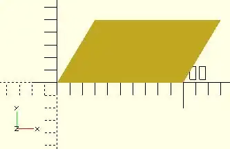
and the same shape with the path vector:
polygon([[0,0],[100,0],[130,50],[30,50]], paths=[[0,1,2,3]]);
Note that the path can index the points starting with any one of them, so long as the list of references "walks" around the outside of the shape.
Example With One Hole
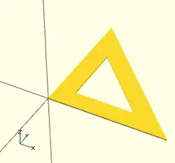
Using vector literals to draw a triangle with its center cut out. Note the two paths:
polygon(
   [[0,0],[100,0],[0,100],[10,10],[80,10],[10,80]],
   [[0,1,2],[3,4,5]]
   );
And using variables:
triangle_points =[[0,0],[100,0],[0,100],[10,10],[80,10],[10,80]];
triangle_paths =[[0,1,2],[3,4,5]];
polygon(triangle_points,triangle_paths);
When there is a shape wholly inside the bounds of another it makes a hole.
Example With Multiple Holes
[Note: Requires version 2015.03] (for use of concat())
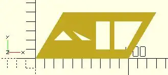
We are using "a" for the point lists and "b" for their paths:
a0 = [[0,0],[100,0],[130,50],[30,50]];     // outer boundary
b0 = [1,0,3,2];
a1 = [[20,20],[40,20],[30,30]];            // hole 1
b1 = [4,5,6];
a2 = [[50,20],[60,20],[40,30]];            // hole 2
b2 = [7,8,9];
a3 = [[65,10],[80,10],[80,40],[65,40]];    // hole 3
b3 = [10,11,12,13];
a4 = [[98,10],[115,40],[85,40],[85,10]];   // hole 4
b4 = [14,15,16,17];
a  = concat( a0,a1,a2,a3,a4 ); // merge all points into "a"
b  = [b0,b1,b2,b3,b4]; // place all paths into a vector
polygon(a,b);
      //alternate
polygon(a,[b0,b1,b2,b3,b4]);
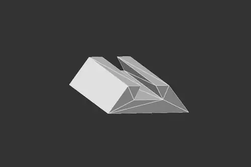
2D to 3D by Extrusion
A polygon may be the basis for an extrusion, just as any of the 2D primitives can. This example script may be used to draw the shape in this image:
Import a 2D Shape From a DXF
[Deprecated: import_dxf() will be removed in a future release. Use Use import() Object Module instead. instead]
Read a DXF file and create a 2D shape.
Example
linear_extrude(height = 5, center = true)
		import_dxf(file = "example009.dxf", layer = "plate");
Example with Import()
linear_extrude(height = 5, center = true)
		import(file = "example009.dxf", layer = "plate");