OpenSCAD User Manual/3D Modelling
Primitive Solids
Cube() Object Module
Creates a cube or rectangular prism (i.e., a "box") in the first octant. When center is true, the cube is centered on the origin. Argument names are optional if given in the order shown here.
cube(size = [x,y,z], center = true/false);
cube(size =  x ,     center = true/false);
- parameters:
- size
- single value, cube with all sides this length
- 3 value array [x,y,z], rectangular prism with dimensions x, y and z.
- center
- false (default), 1st (positive) octant, one corner at (0,0,0)
- true, cube is centered at (0,0,0)
- size
default values: cube(); yields: cube(size = [1, 1, 1], center = false);
- examples:
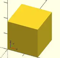
equivalent scripts for this example
 cube(size = 18);
 cube(18);
 cube([18,18,18]);
 .
 cube(18,false);
 cube([18,18,18],false);
 cube([18,18,18],center=false);
 cube(size = [18,18,18], center = false);
 cube(center = false,size = [18,18,18] );
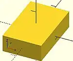
equivalent scripts for this example
 cube([18,28,8],true);
 box=[18,28,8];cube(box,true);
Sphere() Object Module
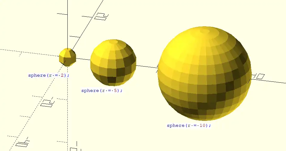
With default parameters this module draws a unit sphere at the origin of the coordinate system, centered vertically on the X-Y plane. It appears as a five sided polyhedron when $fn is zero per the smoothness variables.
default sphere( 1, $fn = 0, $fa = 12, $fs = 2 )
Parameters
- 1) r
- non-negative float, radius
- d
- non-negative float, diameter
- $fn, $fs, $fa
- Smoothness settings, see Rendering: Curve_Smoothness
Radius
The distance from the sphere's center to its surface. A negative value will emit a warning and draw nothing. The smoothness of the surface is determined by the smoothness parameters, $fn, $fs, $fa
Diameter
This must be given as a named parameter.
Usage Examples
sphere();       // radius = 1 by default
sphere(r = 2);
sphere(d = 4);  // same size as previous
To draw a very smooth sphere with a 2 mm radius:
sphere(2, $fn=100);
// also creates a 2mm high resolution sphere but this one
// does not have as many small triangles on the poles of the sphere
sphere(2, $fa=5, $fs=0.1);
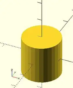
Cylinder() Object Module
Creates a cylinder or cone centered about the z axis.
Called with no arguments, and $fn at its default, the module creates a 1 unit tall, pentagonal solid on the X-Y plane that is inscribed in a unit circle.
Parameter names are optional if the first three are given in the order of height, radius 1 (bottom radius), and radius 2 (top radius) as seen here:
cylinder(h, r1, r2);
Omitting r1 or r2 leaves them at their default values of one resulting in a truncated cone (a Conical Frustum). The named parameters may be given in any order, but for any of the diameter related ones only the first given is used. Giving a diameter/radius value of zero results in a cone shape, and setting both to zero make no shape at all.
- Parameters
- h : (pos 1) height of the cylinder, must be greater than zero
- r1 : (pos 2) radius of bottom circular face.
- r2 : (pos 3) radius of top circular face.
- center : (pos 4)
- false (default), height is from the X-Y plane to positive Z
- true height is centered vertically on the X-Y plane
- r : radius of both end faces
- d : diameter of both end faces. [Note: Requires version 2014.03]
- d1 : diameter of bottom circular face. [Note: Requires version 2014.03]
- d2 : diameter of top circular face. [Note: Requires version 2014.03]
- $fa : minimum angle (in degrees) of each fragment.
- $fs : minimum circumferential length of each fragment.
- $fn : fixed number of fragments in 360 degrees. Values of 3 or more override $fa and $fs
- $fa, $fs and $fn must be named parameters. click here for more details,.
default values:
 cylinder($fn = 0, $fa = 12, $fs = 2, h = 1, r1 = 1, r2 = 1, center = false);
 cylinder($fn = 0, $fa = 12, $fs = 2, h = 1, d1 = 1, d2 = 1, center = false); // radius = 0.5
All of the following calls result in this conic frustum:

cylinder(h=15, r1=9.5, r2=19.5, center=false);
cylinder(  15,    9.5,    19.5, false);
cylinder(  15,    9.5,    19.5);
cylinder(  15,    9.5, d2=39  );
cylinder(  15, d1=19,  d2=39  );
cylinder(  15, d1=19,  r2=19.5);
All of these result in this cone:

cylinder(h=15, r1=10, r2=0, center=true);
cylinder(  15,    10,    0,        true);
cylinder(h=15, d1=20, d2=0, center=true);
-
 center = false
 -
 center = true
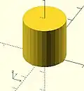
equivalent scripts
 cylinder(h=20, r=10, center=true);
 cylinder(  20,   10, 10,true);
 cylinder(  20, d=20, center=true);
 cylinder(  20,r1=10, d2=20, center=true);
 cylinder(  20,r1=10, d2=2*10, center=true);
- use of $fn
Larger values of $fn create smoother surfaces at the cost of greater rendering time. A good practice is to set it in the range of 10 to 20 during development of a shape, then change to a value larger than 30 for rendering image or exporting shape files.
However, use of small values can produce some interesting non circular objects. A few examples are show here:


scripts for these examples
 cylinder(20,20,20,$fn=3);
 cylinder(20,20,00,$fn=4);
 cylinder(20,20,10,$fn=4);
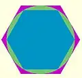
- undersized holes
Using cylinder() with difference() to place holes in objects creates undersized holes. This is because circular paths are approximated with polygons inscribed within in a circle. The points of the polygon are on the circle, but straight lines between are inside. To have all of the hole larger than the true circle, the polygon must lie wholly outside of the circle (circumscribed). Modules for circumscribed holes
script for this example
 poly_n = 6;
 color("blue") translate([0, 0, 0.02]) linear_extrude(0.1) circle(10, $fn=poly_n);
 color("green") translate([0, 0, 0.01]) linear_extrude(0.1) circle(10, $fn=360);
 color("purple") linear_extrude(0.1) circle(10/cos(180/poly_n), $fn=poly_n);
In general, a polygon of radius has a radius to the midpoint of any side as . If only the midpoint radius is known (for example, to fit a hex key into a hexagonal hole), then the polygon radius is .


Polyhedron() Object Module
A polyhedron is the most general 3D primitive solid. It can be used to create any regular or irregular shape including those with concave as well as convex features. Curved surfaces are approximated by a series of flat surfaces.
polyhedron( points = [ [X0, Y0, Z0], [X1, Y1, Z1], ... ], triangles = [ [P0, P1, P2], ... ], convexity = N);   // before 2014.03
polyhedron( points = [ [X0, Y0, Z0], [X1, Y1, Z1], ... ], faces = [ [P0, P1, P2, P3, ...], ... ], convexity = N);   // 2014.03 & later
Parameters
- points
- vector of [x,y,z] vertices. Points may be defined in any order.
- triangles
- [Deprecated: triangles will be removed in a future release. Use Use
facesparameter instead instead] Vector of triangles that enclose the solid. Triangles are vectors containing three indices into the points vector.
- faces
- [Note: Requires version 2014.03] Vector of faces that collectively enclose the solid. Each face is a vector containing the indices (0 based) of 3 or more points from the points vector. Faces may be defined in any order, but the points of each face must be ordered correctly (see below). Define enough faces to fully enclose the solid, with no overlap. If points that describe a single face are not on the same plane, the face is automatically split into triangles as needed.
- convexity
- Integer, default=1
Facing and Points Order
In the list of faces, for each face it is arbitrary which point you start with, but the points of the face (referenced by the index into the list of points) must be ordered in clockwise direction when looking at each face from outside inward. The back is viewed from the back, the bottom from the bottom, etc.
Another way to remember this ordering requirement is to use the left-hand rule. Using your left hand, stick your thumb up and curl your fingers as if giving the thumbs-up sign, point your thumb away from the face, and order the points in the direction your fingers curl (this is the opposite of the STL file format convention, which uses a "right-hand rule"). Try this on the example below.
Example 1
Using polyhedron to generate a rectangular prism [ 10, 7, 5 ] :
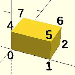
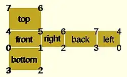
CubePoints = [
  [  0,  0,  0 ],  //0
  [ 10,  0,  0 ],  //1
  [ 10,  7,  0 ],  //2
  [  0,  7,  0 ],  //3
  [  0,  0,  5 ],  //4
  [ 10,  0,  5 ],  //5
  [ 10,  7,  5 ],  //6
  [  0,  7,  5 ]]; //7

CubeFaces = [
  [0,1,2,3],  // bottom
  [4,5,1,0],  // front
  [7,6,5,4],  // top
  [5,6,2,1],  // right
  [6,7,3,2],  // back
  [7,4,0,3]]; // left

polyhedron( CubePoints, CubeFaces );
equivalent descriptions of the bottom face
  [0,1,2,3],
  [0,1,2,3,0],
  [1,2,3,0],
  [2,3,0,1],
  [3,0,1,2],
  [0,1,2],[2,3,0],   // 2 tris with no overlap
  [1,2,3],[3,0,1],
  [1,2,3],[0,1,3],
- Example 2 A square base pyramid:
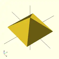
polyhedron(
  points=[ [10,10,0],[10,-10,0],[-10,-10,0],[-10,10,0], // the base
           [0,0,10]  ],                       // the apex point
  faces=[ [0,1,4],[1,2,4],[2,3,4],[3,0,4],    // each triangle side
          [1,0,3],[2,1,3] ]                   // two triangles for square base
 );
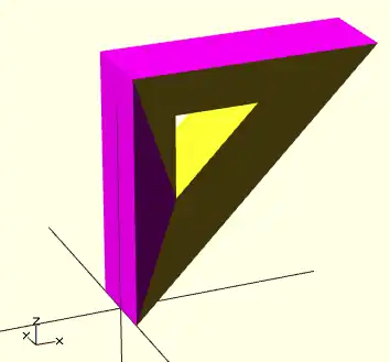
Example 3 A triangular prism
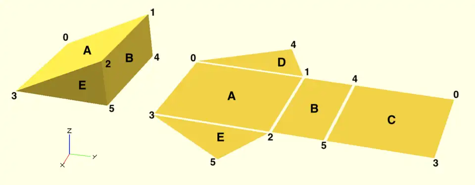
module prism(l, w, h) {
    polyhedron(// pt      0        1        2        3        4        5
               points=[[0,0,0], [0,w,h], [l,w,h], [l,0,0], [0,w,0], [l,w,0]],
               // top sloping face (A)
               faces=[[0,1,2,3],
               // vertical rectangular face (B)
               [2,1,4,5],
               // bottom face (C)
               [0,3,5,4],
               // rear triangular face (D)
               [0,4,1],
               // front triangular face (E)
               [3,2,5]]
               );}
prism(10, 10, 5);
Debugging Polyhedra
Mistakes in defining polyhedra include not having all faces in clockwise order (viewed from outside - a bottom need to be viewed from below), overlap of faces and missing faces or portions of faces. As a general rule, the polyhedron faces should also satisfy manifold conditions:
- exactly two faces should meet at any polyhedron edge.
- if two faces have a vertex in common, they should be in the same cycle face-edge around the vertex.
The first rule eliminates polyhedra like two cubes with a common edge and not watertight models; the second excludes polyhedra like two cubes with a common vertex.
When viewed from the outside, the points describing each face must be in the same clockwise order, and provides a mechanism for detecting counterclockwise. When the thrown together view (F12) is used with F5, CCW faces are shown in pink. Reorder the points for incorrect faces. Rotate the object to view all faces. The pink view can be turned off with F10.
OpenSCAD allows, temporarily, commenting out part of the face descriptions so that only the remaining faces are displayed. Use // to comment out the rest of the line. Use /* and */ to start and end a comment block. This can be part of a line or extend over several lines. Viewing only part of the faces can be helpful in determining the right points for an individual face. Note that a solid is not shown, only the faces. If using F12, all faces have one pink side. Commenting some faces helps also to show any internal face.
CubeFaces = [
/* [0,1,2,3],  // bottom
   [4,5,1,0],  // front */
   [7,6,5,4],  // top
/* [5,6,2,1],  // right
   [6,7,3,2],  // back */
   [7,4,0,3]]; // left
After defining a polyhedron, its preview may seem correct. The polyhedron alone may even render fine. However, to be sure it is a valid manifold and that it can generate a valid STL file, union it with any cube and render it (F6). If the polyhedron disappears, it means that it is not correct. Revise the winding order of all faces and the two rules stated above.
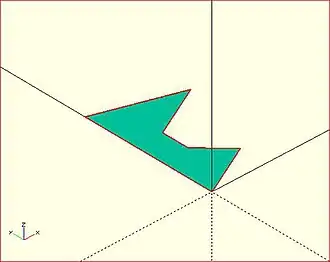
Mis-ordered faces
Example 4
a more complex polyhedron with mis-ordered faces When you select 'Thrown together' from the view menu and compile (preview F5) the design (not compile and render!) the preview shows the mis-oriented polygons highlighted. Unfortunately this highlighting is not possible in the OpenCSG preview mode because it would interfere with the way the OpenCSG preview mode is implemented.)
Below you can see the code and the picture of such a problematic polyhedron, the bad polygons (faces or compositions of faces) are in pink.
// Bad polyhedron
polyhedron
    (points = [
	       [0, -10, 60], [0, 10, 60], [0, 10, 0], [0, -10, 0], [60, -10, 60], [60, 10, 60],
	       [10, -10, 50], [10, 10, 50], [10, 10, 30], [10, -10, 30], [30, -10, 50], [30, 10, 50]
	       ],
     faces = [
		  [0,2,3],   [0,1,2],  [0,4,5],  [0,5,1],   [5,4,2],  [2,4,3],
                  [6,8,9],  [6,7,8],  [6,10,11], [6,11,7], [10,8,11],
		  [10,9,8], [0,3,9],  [9,0,6], [10,6, 0],  [0,4,10],
                  [3,9,10], [3,10,4], [1,7,11],  [1,11,5], [1,7,8],
                  [1,8,2],  [2,8,11], [2,11,5]
		  ]
     );
A correct polyhedron would be the following:
polyhedron
    (points = [
	       [0, -10, 60], [0, 10, 60], [0, 10, 0], [0, -10, 0], [60, -10, 60], [60, 10, 60],
	       [10, -10, 50], [10, 10, 50], [10, 10, 30], [10, -10, 30], [30, -10, 50], [30, 10, 50]
	       ],
     faces = [
		  [0,3,2],  [0,2,1],  [4,0,5],  [5,0,1],  [5,2,4],  [4,2,3],
                  [6,8,9],  [6,7,8],  [6,10,11],[6,11,7], [10,8,11],
		  [10,9,8], [3,0,9],  [9,0,6],  [10,6, 0],[0,4,10],
                  [3,9,10], [3,10,4], [1,7,11], [1,11,5], [1,8,7],
                  [2,8,1],  [8,2,11], [5,11,2]
		  ]
     );
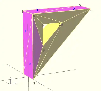
Face Orientation in Polyhedra
If you don't really understand "orientation", try to identify the mis-oriented pink faces and then invert the sequence of the references to the points vectors until you get it right. E.g. in the above example, the third triangle ([0,4,5]) was wrong and we fixed it as [4,0,5]. Remember that a face list is a circular list. In addition, you may select "Show Edges" from the "View Menu", print a screen capture and number both the points and the faces. In our example, the points are annotated in black and the faces in blue. Turn the object around and make a second copy from the back if needed. This way you can keep track.
- Clockwise technique
Orientation is determined by clockwise circular indexing. This means that if you're looking at the triangle (in this case [4,0,5]) from the outside you'll see that the path is clockwise around the center of the face. The winding order [4,0,5] is clockwise and therefore good. The winding order [0,4,5] is counter-clockwise and therefore bad. Likewise, any other clockwise order of [4,0,5] works: [5,4,0] & [0,5,4] are good too. If you use the clockwise technique, you'll always have your faces outside (outside of OpenSCAD, other programs do use counter-clockwise as the outside though).
Think of it as a "left hand rule":
If you place your left hand on the face with your fingers curled in the direction of the order of the points, your thumb should point outward. If your thumb points inward, you need to reverse the winding order.
Succinct description of a 'Polyhedron'
- Points define all of the points/vertices in the shape.
- Faces is a list of polygons that connect up the points/vertices.
Each point, in the point list, is defined with a 3-tuple x,y,z position specification. Points in the point list are automatically enumerated starting from zero for use in the faces list (0,1,2,3,... etc).
Each face, in the faces list, is defined by selecting 3 or more of the points (using the point order number) out of the point list.
e.g. faces=[ [0,1,2] ] defines a triangle from the first point (points are zero referenced) to the second point and then to the third point.
When looking at any face from the outside, the face must list all points in a clockwise order.
Repetitions in a Point List
The point list of the polyhedron definition may have repetitions. When two or more points have the same coordinates they are considered the same polyhedron vertex. So, the following polyhedron:
points = [[ 0, 0, 0], [10, 0, 0], [ 0,10, 0],
          [ 0, 0, 0], [10, 0, 0], [ 0,10, 0],
          [ 0,10, 0], [10, 0, 0], [ 0, 0,10],
          [ 0, 0, 0], [ 0, 0,10], [10, 0, 0],
          [ 0, 0, 0], [ 0,10, 0], [ 0, 0,10]];
polyhedron(points, [[0,1,2], [3,4,5], [6,7,8], [9,10,11], [12,13,14]]);
define the same tetrahedron as:
points = [[0,0,0], [0,10,0], [10,0,0], [0,0,10]];
polyhedron(points, [[0,2,1], [0,1,3], [1,2,3], [0,3,2]]);
Extrusion is the process of creating an object with a fixed cross-sectional profile. OpenSCAD provides two commands to create 3D solids from a 2D shape: linear_extrude() and rotate_extrude().
Linear extrusion is similar to pushing clay through a die with a profile shape cut through it.
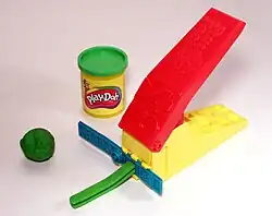
Rotational extrusion is similar to the process of applying a profile to clay spinning on a potter's wheel.

Both extrusion methods work on a (possibly disjointed) 2D shape normally drawn in the relevant plane (see below).
linear_extrude() Operator Module
A Linear Extrusion must be given a 2D child object, as in this statement:
linear_extrude( h=2 ) square();
This child object is first projected onto the X-Y plane along the Z axis to create the starting face of the extrusion. The start face is duplicated at the Z position given by the height parameter to create the extrusion's end face. The extrusion is then formed by creating a surface that joins each point along the edges of the two faces.
The 2D shape may be any 2D primitive shape, a 2d polygon, an imported 2D drawing, or a boolean combination of them. The 2D shape may have a Z value that moves it out of the X-Y plane, and it may even be rotated out of parallel with it. As stated above, the extrusion's starting face is the projection of the 2D shape onto the X-Y plane, which, if it is rotated, will have the effect of fore-shortening it normal to the axis of the rotation.
Using a 3D object as the extrusion's child will cause a compile time error. Including a 3D object in a composition of 2D objects (formed using boolean combinations on them) will be detected, the 3D object(s) will be deleted from it and the remaining 2D objects will be the basis for projecting their shape onto the X-Y plane.
Parameters For Linear Extrusion
There are no required parameters. The default operation is to extrude the child by 100 units vertically from the X-Y Plane, centered on the [0,0] origin.
- 1) height
- a non-negative integer, default 100, giving the length of the extrusion
- 2) v - twist axis vector
- a vector of 3 signed decimal values, default [0,0,1], used as an eigen vector specifying the axis of rotation for the twist. [Note: Requires version Development snapshot]
- 3) center
- a boolean, default false, that, when true, causes the resulting solid to be vertically centered at the X-Y plane.
- 4) convexity
- a non-negative integer, default 1, giving a measure of the complexity of the generated surface. See the Section on Convexity later on this page.
- 5) twist
- a signed decimal, default 0.0, specifying how many degrees of twist to apply between the start and end faces of the extrusion. 180 degrees is a half twist, 360 is all the way around, and so on.
- 6) scale
- either : a non-negative, decimal value, default 1.0, minimum 0.0, that specifies the factor by which the end face should be scaled up, or down, in size from that of the start face.
- or : an [x,y] vector that scales the extrusion in the X and Y directions separately.
- 7) slices
- a non-negative integer for the number of rows of polygons that the extr.
- 8) segments
- Similar to slices but adding points on the polygon's segments without changing the polygon's shape.
- h
- a named parameter, synonym to height
- $fn $fs $fa
- Special Parameters - given as named parameters.
Center
This parameter affects only affects the vertical position or the extrusion. Its X-Y position is always that of the projection that sets its starting face.
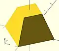
Scale
This is multiplicative factor that affects the size of extrusion's end face. As such 1.0 means no change, a value greater than one expands the end face, and a value between 0.001 and less than 1 shrinks it. A value of 0.0 causes the end face to degenerate to a point, turning the extrusion into a pyramid, cone, or complex pointy shape according to what the starting shape is.
Using the vector form sets the scale factor in the X and Y directions separately
Twist
Twist is applied, by default, as a rotation about the Z Axis. When the start face is at the origin a twist creates a spiral out of any corners in the child shape. If the start face is translated away from the origin the twist creates a spring shape.
A positive twist rotates clockwise, negative twist the opposite.
Twist Axis Vector
The second parameter is an [x,y,z] eigen vector that specifies the axis of rotation of the applied twist. The ratios of the three dimensional values to their respective coordinate axes specify the tilt away from the default axis, [0,0,1], the Z-Axis. For instance, v=[cos(45),0,1] tilts the extrusion at 45 degrees to the X axis.
The start and end faces are always normal to the Z-axis, even when the twist axis is tilted. The extruded and twisted surfaces are thus distorted from what might be expected in an extruded shape. The more expected result may be achieved by applying a rotation to then twisted extrusion on the Z Axis to tilt it into the desired position.
$fn, $fa, $fs Special Parameters
The special variables must be given as named parameters and are applied to the extrusion, overriding the global setting. When the same special variables are set on the base shape its values override their use as parameters on the extrusion.
Extrusion From Imported DXF
Example of linear extrusion of a 2D object imported from a DXF file.
linear_extrude(height = fanwidth, center = true, convexity = 10)
   import (file = "example009.dxf", layer = "fan_top");

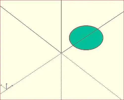
A Unit Circle with No Twist
Generate an extrusion from a circle 2 units along the X Axis from the origin, centered vertically on the X-Y plane, with no twist. The extrusion appears to have a pentagonal cross-section because the extrusion's child is a 2D circle with the default value for $fn.
linear_extrude(height = 10, center = true, convexity = 10, twist = 0)
    translate([2, 0, 0])
        circle(r = 1);

A Unit Circle Twisted Left 100 Degrees
The same circle, but now with 100 degrees of counter-clockwise twist.
linear_extrude(height = 10, center = true, convexity = 10, twist = -100)
    translate([2, 0, 0])
        circle(r = 1);

A Unit Circle Twisted Right 100 Degrees
The same circle, but now with 100 degrees of clockwise twist.
linear_extrude(height = 10, center = true, convexity = 10, twist = 100)
    translate([2, 0, 0])
        circle(r = 1);

A Unit Circle Twisted Into a Spiral
The same circle, but made into a spiral by 500 degrees of counter-clockwise twist.
linear_extrude(height = 10, center = true, convexity = 10, twist = -500)
    translate([2, 0, 0])
        circle(r = 1);
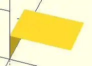
Center
With center=false, the default, the extrusion is based on the X-Y plane and rises up in the positive Z direction.

When true it is centered vertically at the X-Y plane, as seen here:
Mesh Refinement
The slices parameter defines the number of intermediate points along the Z axis of the extrusion. Its default increases with the value of twist. Explicitly setting slices may improve the output refinement. Additional the segments parameter adds vertices (points) to the extruded polygon resulting in smoother twisted geometries. Segments need to be a multiple of the polygon's fragments to have an effect (6 or 9.. for a circle($fn=3), 8,12.. for a square() ).

linear_extrude(height = 10, center = false, convexity = 10, twist = 360, slices = 100)
translate([2, 0, 0])
circle(r = 1);
The special variables $fn, $fs and $fa can also be used to improve the output. If slices is not defined, its value is taken from the defined $fn value.

linear_extrude(height = 10, center = false, convexity = 10, twist = 360, $fn = 100)
translate([2, 0, 0])
circle(r = 1);
Scale
Scales the 2D shape by this value over the height of the extrusion. Scale can be a scalar or a vector:
 linear_extrude(height = 10, center = true, convexity = 10, scale=3)
 translate([2, 0, 0])
 circle(r = 1);

 linear_extrude(height = 10, center = true, convexity = 10, scale=[1,5], $fn=100)
 translate([2, 0, 0])
 circle(r = 1);

Note that if scale is a vector, the resulting side walls may be nonplanar. Use twist=0 and the slices parameter to avoid asymmetry.
 linear_extrude(height=10, scale=[1,0.1], slices=20, twist=0)
 polygon(points=[[0,0],[20,10],[20,-10]]);
Using with imported SVG
A common usage of this function is to import a 2D svg
 linear_extrude(height = 10, center = true)
 import("knight.svg");
rotate_extrude() Operator Module
Rotational extrusion spins a 2D shape around the Z-axis to form a solid which has rotational symmetry. One way to think of this operation is to imagine a Potter's wheel placed on the X-Y plane with its axis of rotation pointing up towards +Z. Then place the to-be-made object on this virtual Potter's wheel (possibly extending down below the X-Y plane towards -Z). The to-be-made object is the cross-section of the object on the X-Y plane (keeping only the right half, X >= 0). That is the 2D shape that will be fed to rotate_extrude() as the child in order to generate this solid. Note that the object started on the X-Y plane but is tilted up (rotated +90 degrees about the X-axis) to extrude.
Since a 2D shape is rendered by OpenSCAD on the X-Y plane, an alternative way to think of this operation is as follows: spins a 2D shape around the Y-axis to form a solid. The resultant solid is placed so that its axis of rotation lies along the Z-axis.
Just like the linear_extrude, the extrusion is always performed on the projection of the 2D polygon to the XY plane. Transformations like rotate, translate, etc. applied to the 2D polygon before extrusion modify the projection of the 2D polygon to the XY plane and therefore also modify the appearance of the final 3D object.
- A translation in Z of the 2D polygon has no effect on the result (as also the projection is not affected).
- A translation in X increases the diameter of the final object.
- A translation in Y results in a shift of the final object in Z direction.
- A rotation about the X or Y axis distorts the cross section of the final object, as also the projection to the XY plane is distorted.
Don't get confused, as OpenSCAD displays 2D polygons with a certain height in the Z direction, so the 2D object (with its height) appears to have a bigger projection to the XY plane. But for the projection to the XY plane and also for the later extrusion only the base polygon without height is used.
You cannot use rotate_extrude to produce a helix or screw thread. Doing this properly can be difficult, so it's best to find a thread library to make them for you.
The 2D shape must lie completely on either the right (recommended) or the left side of the Y-axis. More precisely speaking, every vertex of the shape must have either x >= 0 or x <= 0. If the shape spans the X axis a warning appears in the console windows and the rotate_extrude() is ignored. If the 2D shape touches the Y axis, i.e. at x=0, it must be a line that touches, not a point, as a point results in a zero thickness 3D object, which is invalid and results in a CGAL error. For OpenSCAD versions prior to 2016.xxxx, if the shape is in the negative axis the resulting faces are oriented inside-out, which may cause undesired effects.
Usage
rotate_extrude(angle = 360, start=0, convexity = 2) {...}

In 2021.01 and previous, you must use parameter names due to a backward compatibility issue.
- convexity : If the extrusion fails for a non-trival 2D shape, try setting the convexity parameter (the default is not 10, but 10 is a "good" value to try). See explanation further down.
- angle [Note: Requires version 2019.05] : Defaults to 360. Specifies the number of degrees to sweep, starting at the positive X axis. The direction of the sweep follows the Right Hand Rule, hence a negative angle sweeps clockwise.
- start [Note: Requires version Development snapshot] : Defaults to 0 if angle is specified, and 180 if not. Specifies the starting angle of the extrusion, counter-clockwise from the positive X axis.
- $fa : minimum angle (in degrees) of each fragment.
- $fs : minimum circumferential length of each fragment.
- $fn : fixed number of fragments in 360 degrees. Values of 3 or more override $fa and $fs
- $fa, $fs and $fn must be named parameters. click here for more details,.
Rotate Extrude on Imported DXF
rotate_extrude(convexity = 10)
   import (file = "example009.dxf", layer = "fan_side", origin = fan_side_center);
Examples
→
A simple torus can be constructed using a rotational extrude.
rotate_extrude(convexity = 10)
    translate([2, 0, 0])
        circle(r = 1);
Mesh Refinement
→
Increasing the number of fragments composing the 2D shape improves the quality of the mesh, but takes longer to render.
rotate_extrude(convexity = 10)
    translate([2, 0, 0])
        circle(r = 1, $fn = 100);
→
The number of fragments used by the extrusion can also be increased.
rotate_extrude(convexity = 10, $fn = 100)
    translate([2, 0, 0])
        circle(r = 1, $fn = 100);
Using the parameter angle (with OpenSCAD versions 2016.xx), a hook can be modeled .
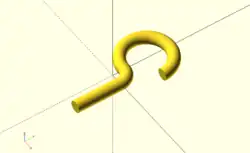
eps = 0.01;
translate([eps, 60, 0])
    rotate_extrude(angle=270, convexity=10)
        translate([40, 0]) circle(10);
rotate_extrude(angle=90, convexity=10)
    translate([20, 0]) circle(10);
translate([20, eps, 0])
    rotate([90, 0, 0]) cylinder(r=10, h=80+eps);
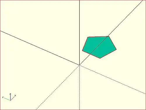
Extruding a Polygon
Extrusion can also be performed on polygons with points chosen by the user.
Here is a simple polygon and its 200 step rotational extrusion. (Note it has been rotated 90 degrees to show how the rotation appears; the rotate_extrude() needs it flat).
rotate([90,0,0]) polygon( points=[[0,0],[2,1],[1,2],[1,3],[3,4],[0,5]] );
rotate_extrude($fn=200) polygon( points=[[0,0],[2,1],[1,2],[1,3],[3,4],[0,5]] );
→ →
→
For more information on polygons, please see: 2D Primitives: Polygon.
Orientation
If you're making a round 360 degree extrusion, it doesn't matter where it starts. If, on the other hand, you're using $fn to make an extrusion with some specific number of sides, it can matter. With an odd number of sides, there will be a vertex on either the left or the right, and a side opposite it.
With angle not specified, the extrusion starts along the negative X axis, to the left of the origin. With an odd number of sides, there is a vertex on the left and a side on the right. (Note that this is inconsistent with the behavior for angle less than 360, and with the behavior for circle and other round primitives.)
With angle specified, and not equal to 360, the extrusion starts along the positive X axis, to the right of the origin.
For 2021.01 and earlier, if angle is equal to 360, the extrusion starts along the negative X axis, as for angle not being specified.
For the development snapshot, if angle is 360, the extrusion starts along the positive X axis, as for other cases where angle is specified. Explicitly specifying angle=360 thus yields results consistent with other round primitives.
A future release may change this behavior so that when angle is not specified the extrusion starts along the positive X axis, making all of these cases consistent.
start directly controls the start point. [Note: Requires version Development snapshot]
Description of extrude parameters
Parameters Used In All Extrusions
- convexity
- an integer that works as a measure of complexity based on the maximum number of sides a ray might penetrate as it passes through a shape.
For instance, the convexity of a sphere is one and the convexity of a torus is two. From any point of view there is only a single surface showing for a sphere. But with a torus a given pixel may be showing the front most face, the back part of the doughnut, or the background. Setting convexity greater than the default 1 informs the renderer of the need to be more careful in its work.
Arbitrarily setting convexity to 10 should solve most preview rendering issues, at the expense of slowing preview rendering. When a model has several convoluted shapes values more than 15 can slow rendering to the point of freezing the application.
The issue of Convexity is an issue in Preview Rendering.
Parameters For Linear Extrusion
- height
- a non-negative integer, default 100, giving the length of the extrusion
- center
- a boolean, default false, that, when true, causes the resulting solid to be vertically centered at the X-Y plane.
- twist
- a signed decimal, default 0.0, specifying how many degrees of twist to apply between the start and end faces of the extrusion
- scale
- a non-negative, decimal value, default 1.0, greater than 0.0, that specifies the factor by which the end face should be scaled up, or down, in size from that of the start face.
- a vector containing these values in this order
- [
- slices
- a non-negative integer value that acts on the extruded surface as $fn does, but which is not applied to the child 2D shape.
- segments
- Similar to slices but adding points on the polygon's segments without changing the polygon's shape.
- $fn
- the special variable but applied only to the extrusion
- $fs
- the special variable but applied only to the extrusion
- $fa
- the special variable but applied only to the extrusion
- ]
Note
- centering the extrusion only affects its vertical position. Its X-Y position is always set by its starting face.
- A Scale Factor greater than one increases the size of the extrusion's end face, while a value greater than 0.0 and less than 1 shrink it. A value of 0.0 causes the end face to degenerate to a point, turning the extrusion into a pyramid, cone, or complex pointy shape according to what the starting shape is.
Importing 3D Solids
In older versions of the application files of each format were imported using a module specific to it. These older modules are deprecated in newer versions but are still documented in this page.
Currently the import() Object Module processes each type of file according to its file extension to instantiate imported objects. [Note: Requires version 2015]
There are some other, purpose specific, import methods in the app:
- A '.csg' geometry file
- may be imported by an
include <filename.csg>statement. - A '.png' image
- The import image option of the surface() object module may be used to apply a height map to a surface.
- data in a text file
- The import numeric data of the surface() object module may also be used to apply a height map.
- data in a JSON file
- The import() function may can read structured data into an object that can then be processed by a script.
Include <"filename.csg">
A .csg format file is a type of geometry file exported from OpenSCAD using a subset of its programming language.
As such the shapes described by it may be imported into a program using the include <filename.csg> statement.
Import() Object Module
This is an Object Module that imports geometry for use in the script. The extension on the filename informs the module as to which input processor to use.
The import() function is a separate component for bringing in structured data from a JSON file.
Parameters
- file
- A string containing a filename and extension of form "filename.ext". The location of the file is the same as the script's file. Refer to the File System Issues page for other file path options and platform specific information.
filename- deprecated - a filename of form "filename.ext". Use "file" parameter.
- origin
- vector of form [xcoord,ycoord]
- scale
- number. A scale factor to apply to the model
- width
- number
- height
- number
- dpi
- non-negative integer >= 0.001. The Dots Per Inch value is used importing a SVG or DXF file to correctly size the generated geometry.
- center
- Boolean. When true the object is centered in the X-Y plane at the origin. [Note: Requires version Development snapshot]
- convexity
- non-negative integer. The convexity parameter specifies the maximum number of front sides (or back sides) a ray intersecting the object might penetrate. This parameter is needed only for correctly displaying the object in OpenCSG preview mode and has no effect on the polyhedron rendering. Optional.
- id
- String. For SVG import only, the id of an element or group to import. Optional. [Note: Requires version Development snapshot]
- layer
- For DXF and SVG import only, specify a specific layer to import. Optional.
layername- [Deprecated: layername will be removed in a future release. Use layer instead]
- $fn
- Number, default 0. The number of polygon segments to use when converting circles, arcs, and curves to polygons. [Note: Requires version Development snapshot]
- $fa
- Number, default 12. The minimum angle step to use when converting circles and arcs to polygons. [Note: Requires version Development snapshot]
- $fs
- Number, default 2. The minimum segment length to use when converting circles and arcs to polygons. [Note: Requires version Development snapshot]
3D Geometry Formats
There is a concise comparison of the commonly used file formats in 3D printing on the AnyCubic website that may be of interest.
These are the file formats recognized by import():
- OBJ
- OBJect data file by Wavefront
- AMF
- Additive Manufacturing Files include color, texture, and other meta data in addition to a 3D polygonal geometry but is deprecated as it has not achieved much acceptance in the industry.
- 3MF
- 3D Manufacturing Format XML data file
- CSG
- solid geometry format of OpenSCAD programming language
- STL
- STereoLithography file format by 3D Systems for describing polygons in a 3D coordinate space. Replaced by Additive Manufacturing Format (.amf)
- OFF
- Object File Format
- NEF3
- a CGAL geometry data format from a Nef Polygon object (ref section 15.6). It is used mostly by the OpenSCAD dev group as a debugging tool when building test cases for upstream reporting to CGAL.
2D Geometry Formats
Shapes drawn in two dimensional formats may also be imported by the import() module, as documented in the Import 2D page.
Image Formats
- PNG
- Portable Network Graphics image file. As already mentioned, the surface() method is able to derive a gray scale value from each pixel to apply to a surface as a height map.
import() Function - JSON only
[Note: Requires version Development snapshot]
This function returns an object with the structured data from a valid JSON file. Although it has the same name as the import() Module it is functionally separate in that it may only be used in an assignment statement and may not be the target action of an Operator Module.
/* "people.json" contains:
{"people":[{"name":"Helen", "age":19}, {"name":"Chris", "age":32}]}
*/
pf=import( file = "people.json" );
echo(pf);
people = pf.people;
for( p=people) {
	echo(str( p.name, ": ", p.age));
    }
or even
 people = import( file = "people.json" ).people;
 for( p=people) {
	 echo(str( p.name, ": ", p.age));
     }
both of which give the data about Helen and Chris:
ECHO: { people = [{ age = 19; name = "Helen"; }, { age = 32; name = "Chris"; }]; }
ECHO: "Helen: 19"
ECHO: "Chris: 32"
Surface() Object Module: Apply a Height Map
The Surface module draws a surface based on the Height map information given either as numbers in a text data file, or by interpreting the luminance of each pixel in a PNG image file (only).
The generated surface is normally drawn from the (0,0) origin in the +X,+Y quadrant. The extent of the drawn surface is either:
- data file - the number of columns and rows in the file
- image - the number of pixels in each direction of the image.
To make a surface of size (m,n) there must be n rows of numbers, with m values on each row.
Height values from an image file are massaged to the range of 0-100 and so will not have negative values, unless the invert option changes the sign of all the height values.
Height values are applied starting at the [0,0] corner. The column index and the X coordinate are both increased by one and the next value applied at the next position on the surface. Continue like this to the end of the row and then increase the Y coordinate, and the row index, by one as the row is completed. Repeat until all the rows are processed.
For a data file of size (m,n) the generated surface is grid of squares with the height value applied at the left-lower corner (as seen here). The n-th row of heights will be on the top vertices of the squares along the top edge of the surface:
 ^  [x,y+n] [x+m,y+n]
 |
 y  [x,y]   [x+m,y]
[0,0] x-->
A one unit thick base is drawn downwards under the generated surface from the level of the smallest value in the data file, including when heights have negative values. This means that when least height value is zero the base will extend down to z=-1.
Parameters
- filename
- Required String. The filename may include an absolute or a relative path to the height map data file. There is no default so the .png extension must be explicitly given.
- center
- Optional Boolean, default=
falseto draw in the +X,+Y quadrant. Whentruethe surface is centered on the X-Y origin. - invert
- Optional Boolean, default=false. Limitation: Only applies to image based maps
. Inverts how the pixel values are interpreted into height values.[Note: Requires version 2015.03]
- convexity
- Integer, default=1. Higher values improve preview rendering of complex shapes. Limitation: Only used by OpenCSG Preview
Text Data Format
A text data height map is simply rows of whitespace separated, floating point numbers. The values may be written as integers, floating point with decimal fractions, or using exponential notation such as 1.25e2 for 125.
Hex values are not accepted but may not give a warning.
Consider a data file with n rows and m values on each, thus having size (m,n). The X position of each data point is given by their position along their row, and the Y by the row. The implicit indexing starts at the beginning of the file with the first row being at Y=0 and the first point on each row at X=0. The X and Y positions increment by one until X=m and Y=n, which means that the last row of values is the farthest edge of the generated surface.
The appearance of a hash sign ('#') as the first, non-whitespace character on a line marks it as a comment. A hash mark following numbers on a row cause a lexical fault making the data file unreadable.
Examples Using Data Map
//surface.scad
surface(file = "surface.dat", center = true, convexity = 5);
%translate([0,0,5]) cube([10,10,10], center = true);
The transparent cube shows the extent of the data space, and that the base extends downwards to Y=-1.
#surface.dat
10 9 8 7 6 5 5 5 5 5
 9 8 7 6 6 4 3 2 1 0
 8 7 6 6 4 3 2 1 0 0
 7 6 6 4 3 2 1 0 0 0
 6 6 4 3 2 1 1 0 0 0
 6 6 3 2 1 1 1 0 0 0
 6 6 2 1 1 1 1 0 0 0
 6 6 1 0 0 0 0 0 0 0
 3 1 0 0 0 0 0 0 0 0
 3 0 0 0 0 0 0 0 0 0
Result:

One may use an application like Octave or Matlab to make a data file. This is a small Matlab script that superimposes two sine waves to create a 3D surface:
d = (sin(1:0.2:10)' * cos(1:0.2:10)) * 10;
save("-ascii", "example010.dat", "d");
The data file can then be used to draw the surface three ways:
//draw an instance of the surface
surface(file = "example010.dat", center = true);
//draw another instance, now rotated
translate(v = [70, 0, 0])
  rotate(45, [0, 0, 1])
    surface(file = "example010.dat", center = true);
// and two last instances, intersected
translate(v = [35, 60, 0])
intersection() {
  surface(file = "example010.dat", center = true);
    rotate(45, [0, 0, 1])
      surface(file = "example010.dat", center = true);
}

Image Base Height Maps
[Note: Requires version 2015.03]
Heights are calculated using the linear luminance for the sRGB color space (Y = 0.2126R + 0.7152G + 0.0722B) at each pixel to derive a Grayscale value, which are further scaled to the range [0:100]. For an image with a color space between black (rgb=0,0,0) and white (rgb=1,1,1) the gray scale will be the full range.
For an image with a a narrower range of colors the gray scale is likewise reduced, and the minimum and maximum luminance in the color range set the lowest and highest limits, respectively, on the surface's heights.
Note also that no base is added below the surface as is done for a data file surface. Squares at Z=0, black, do have a surface filled in so the entire area of the surface is continuous.
Normally, with invert=false, the surface will be drawn upwards from the X-Y plane with black being z=0 increasing up to white=100. When invert=true the shape is still drawn starting at the X-Y plane, but now downwards to white=-100.
Currently only PNG (.png) images are supported and only the RGB channels are used. Specifically, the alpha channel is ignored.
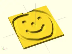
Example Using Invert
// Example 3a - apply a scale to the surface
scale([1, 1, 0.1])
  surface(file = "smiley.png", center = true);
scale([1, 1, 0.1])
  surface(file = "smiley.png", center = true, invert = true);
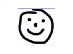
.png)

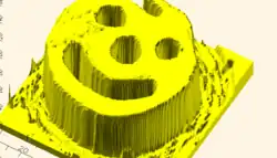
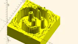
Note that the surfaces are above or, for the inverted surface, below, the X-Y plane, unlike Example 3
Example Grayscale Effects [Note: Requires version 2015.03]
surface(file = "BRGY-Grey.png", center = true, invert = false);
-
 PNG Test File
 -
 3D Surface