OpenSCAD User Manual/Using the 2D Subsystem
Two Dimensional Modelling
All 2D primitives can be transformed with 3D transformations. They are usually used as part of a 3D extrusion. Although they are infinitely thin, they are rendered with a 1-unit thickness.
Note: Trying to subtract with difference() from 3D object will lead to unexpected results in final rendering.
Square Object Module
By default this module draws a unit square in the first quadrant, (+X,+Y), starting at the origin [0,0]. Its four lines have no thickness but the shape is drawn as a 1 unit high, filled plane.
The module's arguments may be written in the order <size>, center=<bool> without being named, but the names may be used as shown in the examples:
Parameters
- size
- has two forms: single value or vector
- single - non-negative float, length of all four sides
- array[x,y] of two non-negative floats, the length of the sides in the x and y directions
- center
- boolean, default false, to set the shape's position in the X-Y plane
Center
When false, as it is by default, the shape will be drawn from its first point at (0,0) in the First Quadrant, (+X,+Y).
With center set to true the shape is drawn centered on the origin.
Examples
Except for being 10 cm square this is a default square:
 square(size = 10, center=false);
 square(10,false);
 square([10,10]);

And to draw a 20x10 rectangle, centered on the origin, like this:
 square([20,10],true);
 a=[20,10]; square(a,true);

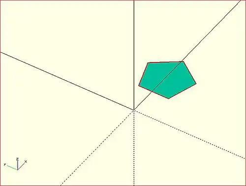
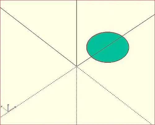
Circle Object Module
By default this module draws a unit circle centered on the origin [0,0] as a pentagon with its starting point on the X-axis at X=1. Its lines have no thickness but the shape is drawn as a 1 unit high, filled plane.
The circle() shape is drawn as if inscribed in a circle of the given radius, starting at a point on the positive x axis.
The argument radius may be given without being named, but the r and d arguments must be named.
Parameters
- 1) radius
- non-negative float, radius of the circle
- r
- non-negative float, radius of the circle
- d
- non-negative float, diameter of the circle
- $fa
- Special Variable
- $fs
- Special Variable
- $fn
- Special Variable
The default circle displays as a pentagram as that is the minimum number of fragments used to approximate a curved shape calculated from the default values for $fs and $fa. To have it draw as a smooth shape increase the $fn value, the minimum number of fragments to draw, to 20 or more (best $fn < 128).
An alternative method to draw a very smooth circle scale is to scale down a very large circle.
scale( 0.001 ) circle(200);

Equivalent scripts for this example
 circle(10);
 circle(r=10);
 circle(d=20);
Drawing an Ellipse
There is no built-in module that for generating an ellipse, but the scale() or resize() operator modules may be used to form an ellipse.
See OpenSCAD User Manual/Transformations
Examples
resize([30,10]) circle(d=20); // change the circle to X and Y sizes

scale([1.5,0.5]) circle(d=20); // apply X and Y factors to circle dimensions

Regular Polygons
There is no built-in module for generating regular polygons.
It is possible to use the special variable $fn rendering parameter to set the number of sides to use when drawing the circle().
circle(r=1, $fn=4); // generate a unit square
Examples
The following script draws these these examples:

translate([-42,  0])
    {circle(20,$fn=3);  %circle(20,$fn=90); }
translate([  0,  0]) circle(20,$fn=4);
translate([ 42,  0]) circle(20,$fn=5);
translate([-42,-42]) circle(20,$fn=6);
translate([  0,-42]) circle(20,$fn=8);
translate([ 42,-42]) circle(20,$fn=12);

color("black"){
    translate([-42,  0,1])text( "3",7);
    translate([  0,  0,1])text( "4",7);
    translate([ 42,  0,1])text( "5",7);
    translate([-42,-42,1])text( "6",7);
    translate([  0,-42,1])text( "8",7);
    translate([ 42,-42,1])text("12",7);
    }
Another way to solve the lack of a built-in module for regular polygons is to write a custom one: module regular_polygon()
Polygon Object Module
The polygon() module draws lines between the points given in a vector of [x,y] coordinates using, optionally, one or more "paths" that specify the order of the points to draw lines between, overriding the "natural" order. Polygons are always created in the X-Y plane and are co-planar by definition.
A polygon is the most general of the 2D objects in that it may be used to generate shapes with both concave and convex edges, have interior holes, and effectively perform boolean operations between shapes defined by paths.
Note that the order of the points sets how the lines will be drawn so complex shapes made with crossing lines can be achieved without using a path argument, but making interior holes do require the use of at least two paths to set the interior and exterior boundary lines.
The determination of which parts of the polygon to fill and to leave empty is handled automatically and it is only the filled parts that will be extruded, if the shape will be used as a basis for that operation. Note also that a shape drawn entirely within a "hole" will be filled in, and any shape its interior will again be a hole, and so on.
polygon(points, paths = undef, convexity = 1);
Parameters
- points
- required and positional - A vector of [x,y] coords that define the points of the polygon
- paths
- optional, default=undef - a vector of vectors of indices into the points vector with no restrictions on order or multiple references.
- convexity
- Integer, default=1 - complex edge geometry may require a higher value value to preview correctly.
Points Parameter A list of X-Y coordinates in this form:
[[1, 1], [1, 4], [3, 4], [3, 1], [1, 1]]
which defines four points and makes it explicit that the last one is the same as the first.
Including the first point twice is not strictly necessary as this:
[[1, 1], [1, 4], [3, 4], [3, 1]]
gives the same result.
Paths Parameter
This optional parameter is a nested vector of paths.
A "path" is a list of index values that reference points in the points vector.
It can explicitly describe a closed loop by its last index being the same as its first, as in:
[1, 2, 3, 4, 1]
but this is equivalent to:
[1, 2, 3, 4]
Paths that cross each other can implicitly perform boolean operations but to cut holes in the interior of the polygon paths will have to be used.
Notice that the points vector is simple list, while each path is a separate vector. This means that paths, that are lists of references to points, have to "know" which points it needs to include. This can be an issue if the polygon is assembled from a number of shapes at run time as the order of adding shapes affects their point's index values. . Convexity
Shapes with a lot of detail in their edges may need the convexity parameter increased to preview correctly. See Convexity
Example With No Holes
This will draw a slanted rectangle:
polygon(points=[[0,0],[100,0],[130,50],[30,50]]);
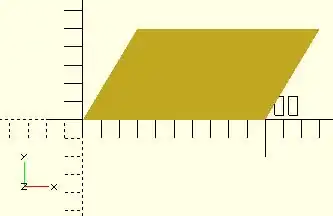
and the same shape with the path vector:
polygon([[0,0],[100,0],[130,50],[30,50]], paths=[[0,1,2,3]]);
Note that the path can index the points starting with any one of them, so long as the list of references "walks" around the outside of the shape.
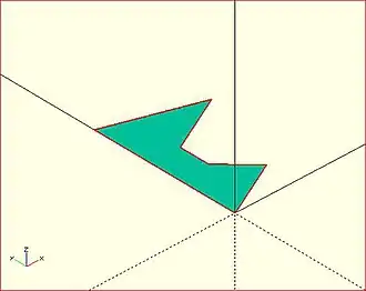
Example With One Hole
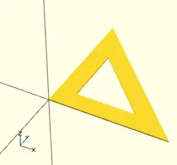
Using vector literals to draw a triangle with its center cut out. Note the two paths:
polygon(
   [[0,0],[100,0],[0,100],[10,10],[80,10],[10,80]],
   [[0,1,2],[3,4,5]]
   );
And using variables:
triangle_points =[[0,0],[100,0],[0,100],[10,10],[80,10],[10,80]];
triangle_paths =[[0,1,2],[3,4,5]];
polygon(triangle_points,triangle_paths);
When there is a shape wholly inside the bounds of another it makes a hole.
Example With Multiple Holes
[Note: Requires version 2015.03] (for use of concat())
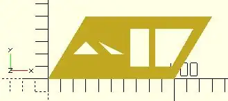
We are using "a" for the point lists and "b" for their paths:
a0 = [[0,0],[100,0],[130,50],[30,50]];     // outer boundary
b0 = [1,0,3,2];
a1 = [[20,20],[40,20],[30,30]];            // hole 1
b1 = [4,5,6];
a2 = [[50,20],[60,20],[40,30]];            // hole 2
b2 = [7,8,9];
a3 = [[65,10],[80,10],[80,40],[65,40]];    // hole 3
b3 = [10,11,12,13];
a4 = [[98,10],[115,40],[85,40],[85,10]];   // hole 4
b4 = [14,15,16,17];
a  = concat( a0,a1,a2,a3,a4 ); // merge all points into "a"
b  = [b0,b1,b2,b3,b4]; // place all paths into a vector
polygon(a,b);
      //alternate
polygon(a,[b0,b1,b2,b3,b4]);
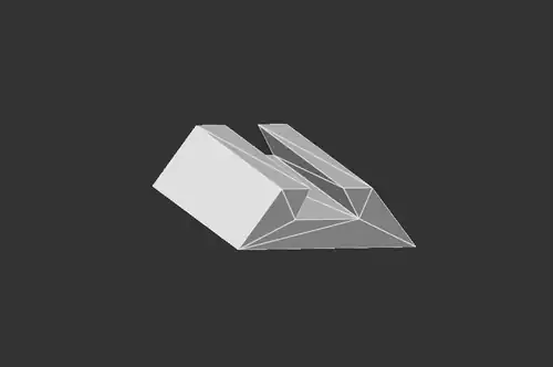
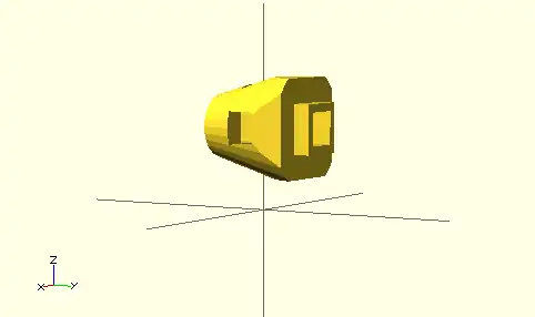
2D to 3D by Extrusion
A polygon may be the basis for an extrusion, just as any of the 2D primitives can. This example script may be used to draw the shape in this image:
Import a 2D Shape From a DXF
[Deprecated: import_dxf() will be removed in a future release. Use Use import() Object Module instead. instead]
Read a DXF file and create a 2D shape.
Example
linear_extrude(height = 5, center = true)
		import_dxf(file = "example009.dxf", layer = "plate");
Example with Import()
linear_extrude(height = 5, center = true)
		import(file = "example009.dxf", layer = "plate");
Text in OpenSCAD
Being able to use text objects as a part of a model is valuable in a lot of design solutions. The text() module is used to draw a string of text as a set of 2D shapes according to the specifications of the given font. The fonts available to use in a script are from the system that OpenSCAD is running in with the addition of those explicitly added by the script itself. To be able to format text, or to align text in relation to other shapes, a script needs information about the text objects that the script is working on, and also about the structure and dimensions of the fonts in use.
text() Object Module
The text() object module draws a single string of text as a 2D geometric object, using fonts installed on the local system or provided as separate font file.
The shape starts at the origin and is drawn along the positive X axis.
Vertical alignment, as set by the valign parameter, is relative to the X axis, and horizontal alignment ( halign ) to the Y axis
[Note: Requires version 2015.03]
Parameters
- text
- String. A single line of any character allowed. Limitation: non-printable ASCII characters like newline and tab rendered as placeholders
- font
- a formatted string with default font of "Liberation Sans:style=Regular"
- size
- non-negative decimal, default=10. The generated text has a height above the baseline of approximately this value, varying for different fonts but typically being slightly smaller.
- halign
- String, default="left". The horizontal alignment for the text. Possible values are "left", "center" and "right".
- valign
- String, default="baseline". The vertical alignment for the text. Possible values are "top", "center", "baseline" and "bottom".
- spacing
- float, default=1. Multiplicative factor that increases or decreases spacing between characters.
- direction
- String, default="ltr". Direction of text. Possible values are "ltr" (left-to-right), "rtl" (right-to-left), "ttb" (top-to-bottom) and "btt" (bottom-to-top).
- language
- String. The language of the text (e.g., "en", "ar", "ch"). Default is "en".
- script
- String, default="latin". The script of the text (e.g. "latin", "arabic", "hani").
- $fn
- higher values generate smoother curves (refer to Special Variables)
Example
_example.png)
text("OpenSCAD");
Font & Style Parameter
The "name" of a font is a string starting with its logical font name and variation, optionally followed by a colon (":") separated list of font specifications like a style selection, and a set of zero or more features.
The common variations in a font family are sans and serif though many others will be seen in the list of fonts available.
Each font variation can be drawn with a style to support textual emphasis.
The default, upright appearance is usually called "Regular" with "Bold", "Italic", and "Bold Italic" being the other three styles commonly included in a font. In general the styles offered by a font may only be known by using the platform's font configuration tools or the OpenSCAD font list dialog.
_font_features_example.png)
In addition to the main font variations, some fonts support features for showing other glyphs like "small-caps" (smcp) where the lower case letters look like scaled down upper case letters, or "old-numbers" (onum) where the numbers are designed in varying heights instead of the way modern lining draws numbers the same size as upper case letters.
The fontfeatures property is appended to the font name after the optional style parameter.
Its value is a semi-colon separated list of feature codes, each prefixed by a plus, "+", to indicate that it is being added,
font = "Linux Libertine G:style=Regular:fontfeatures=+smcp;+onum");
Basic Font Parameter Example
_font_style_example.png)
 square(10);

 translate([15, 15]) {
   text("OpenSCAD", font = "Liberation Sans");
 }

 translate([15, 0]) {
   text("OpenSCAD", font = "Liberation Sans:style=Bold Italic");
 }
Size Parameter
Text size is normally given in points, and a point is 1/72 of an inch high.
The formula to convert the size value to "points" is pt = size/3.937, so a size argument of 3.05 is about 12 points.
Note: Character size the distance from ascent to descent, not from ascent to baseline.
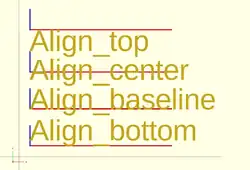
Vertical Alignment
One of these four names must be given as a string to the valign parameter.
- top
- The text is aligned so the top of the tallest character in your text is at the given Y coordinate.
- center
- The text is aligned with the center of the bounding box at the given Y coordinate. This bounding box is based on the actual sizes of the letters, so taller letters and descending below the baseline will affect the positioning.
- baseline
- The text is aligned with the font baseline at the given Y coordinate. This is the default, and is the only option that makes different pieces of text align vertically, as if they were written on lined paper, regardless of character heights and descenders.
- bottom
- The text is aligned so the bottom of the lowest-reaching character in your text is at the given Y coordinate.
Note: only the "baseline" vertical alignment option will ensure correct alignment of texts that use mix of fonts and sizes.
 text = "Align";
 font = "Liberation Sans";

 valign = [
   [  0, "top"],
   [ 40, "center"],
   [ 75, "baseline"],
   [110, "bottom"]
 ];

 for (a = valign) {
   translate([10, 120 - a[0], 0]) {
     color("red") cube([135, 1, 0.1]);
     color("blue") cube([1, 20, 0.1]);
     linear_extrude(height = 0.5) {
       text(text = str(text,"_",a[1]), font = font, size = 20, valign = a[1]);
     }
   }
 }
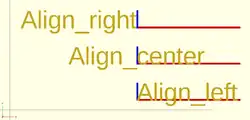
Horizontal Alignment
One of these three names must be given as a string to the halign parameter.
- left
- The text is aligned with the left side of the bounding box at the given X coordinate.
- center
- The text is aligned with the center of the bounding box at the given X coordinate.
- right
- The text is aligned with the right of the bounding box at the given X coordinate.
 text = "Align";
 font = "Liberation Sans";

 halign = [
   [10, "left"],
   [50, "center"],
   [90, "right"]
 ];

 for (a = halign) {
   translate([140, a[0], 0]) {
     color("red") cube([115, 2,0.1]);
     color("blue") cube([2, 20,0.1]);
     linear_extrude(height = 0.5) {
       text(text = str(text,"_",a[1]), font = font, size = 20, halign = a[1]);
     }
   }
 }
Spacing Parameter
Characters in a text element have the size dictated by their glyph in the font being used.
As such their size in X and Y is fixed.
Each glyph also has fixed advance values (it is a vector [a,b], see textmetrics) for the offset to the origin of the next character.
The position of each following character is the advance.x value multiplied by the space value.
Obviously letters in the string can be stretched out when the factor is greater than 1, and can be made to overlap when space is a fraction closer to zero, but interestingly, using a negative value spaces each letter in the opposite of the direction parameter.
Text Examples
Simulating Formatted Text
When text needs to be drawn as if it was formatted it is possible to use translate() to space lines of text vertically.
Fonts that descend below the baseline need to be spaced apart vertically by about 1.4*size to not overlap.
Some word processing programs use a more generous spacing of 1.6*size for "single spacing" and double spacing can use 3.2*size.
Fonts in OpenSCAD
The fonts available for use in a script are thosed:
- registered in the local system
- included in the OpenSCAD installation
- imported at run-time by a program
A call to fontmetrics() using only default settings shows the installation's standard font and settings:
echo( fontmetrics() );
gives this output (formatted for readability)
{
nominal = {
  ascent = 12.5733;
  descent = -2.9433;
  };
max = {
  ascent = 13.6109; descent = -4.2114;
  };
interline = 15.9709;
font = {
  family = "Liberation Sans";
  style = "Regular";
  };
}
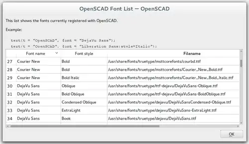
In general the styles offered by a font may only be known by using the platform's font configuration tools or the OpenSCAD font list dialog.
The menu item Help > Font List shows the list of available fonts and the styles included in each one.
None of the platforms OpenSCAD is available on include the Liberation font family so having it as part of the app's installation, and making it the default font, avoids problems of font availability. There are three variations in the family, Mono, Sans, and Serif.
Note: It was previously noted in the docs that fonts may be added to the installation by drag-and-drop of a font file into the editor window, but as of version 2025 Snapshot this is not the case
In the following sample code a True Type Font, Andika, has been added to the system fonts using its Font Management service.
It is also possible to add fonts to a particular project by importing them with the use statement in this form:
text( "sample", font="Andika:style=bold" ); // installed in system fonts

use <Andika-Italic.ttf>;

translate( [0,-10, 0] )
    color("green")
        text( "test", font="Andika:style=italic");
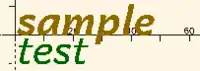
Supported font file formats are TrueType fonts (*.ttf) and OpenType fonts (*.otf). Once a file is registered to the project the details of the fonts in it may be seen in the font list dialog (see image) so that the logical font names, variations, and their available styles are available for use in the project.
3D Text by Extrusion
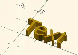
Text can be changed from a 2 dimensional object into a 3D object by using the linear_extrude function.
//3d Text Example
linear_extrude(4)
    text("Text");
Metrics
[Note: Requires version Development snapshot]
textmetrics() Function
The textmetrics() function accepts the same parameters as text(), and returns an object describing how the text would be rendered.
The returned object has these members:
- position
- a vector [X,Y], the origin of the first glyph, thus the lower-left corner of the drawn text.
- size
- a vector [a,b], the size of the generated text.

measurements of a glyph - ascent
- positive float, the amount that the text extends above the baseline.
- descent
- negative float, the amount that the text extends below the baseline.
- offset
- a vector default [0, 0], the lower-left corner of the box containing the text, including inter-glyph spacing before the first glyph.
- advance
- a vector default [153.09, 0], amount of space to leave to any following text.
This example displays the text metrics for the default font used by OpenSCAD:
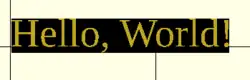
s = "Hello, World!";
size = 20;
font = "Liberation Serif";

tm = textmetrics(s, size=size, font=font);
echo(tm);
translate([0,0,1])
    text("Hello, World!", size=size, font=font);
color("black") translate(tm.position)
    square(tm.size); // "size" is of the bounding box
displays (formatted for readability):
ECHO: {
   position = [0.7936, -4.2752];
   size = [149.306, 23.552];
   ascent = 19.2768;
   descent = -4.2752;
   offset = [0, 0];
   advance = [153.09, 0];
   }
fontmetrics() Function
The fontmetrics() function accepts a font size and a font name, both optional, and returns an object describing global characteristics of the font.
Parameters
- size
- Decimal, optional. The size of the font, as described above for
text().
- font
- String, optional. The name of the font, as described above for
text().
Note that omitting the size and/or font may be useful to get information about the default font.
Returns an object:
- nominal: usual dimensions for a glyph:
- ascent: height above the baseline
- descent: depth below the baseline
- max: maximum dimensions for a glyph:
- ascent: height above the baseline
- descent: depth below the baseline
- interline: design distance from one baseline to the next
- font: identification information about the font:
- family: the font family name
- style: the style (Regular, Italic, et cetera)
echo(fontmetrics(font="Liberation Serif"));
yields (reformatted for readability):
   ECHO: {
       nominal = {
           ascent = 12.3766;
           descent = -3.0043;
       };
       max = {
           ascent = 13.6312;
           descent = -4.2114;
       };
       interline = 15.9709;
       font = {
           family = "Liberation Serif";
           style = "Regular";
       };
   }
Using the projection() function, you can create 2d drawings from 3d models, and export them to the dxf format. It works by projecting a 3D model to the (x,y) plane, with z at 0. If cut=true, only points with z=0 are considered (effectively cutting the object), with cut=false(the default), points above and below the plane are considered as well (creating a proper projection).
Example: Consider example002.scad, that comes with OpenSCAD.

Then you can do a 'cut' projection, which gives you the 'slice' of the x-y plane with z=0.
projection(cut = true) example002();

You can also do an 'ordinary' projection, which gives a sort of 'shadow' of the object onto the xy plane.
projection(cut = false) example002();

Another Example
You can also use projection to get a 'side view' of an object. Let's take example002, rotate it, and move it up out of the X-Y plane:
translate([0,0,25]) rotate([90,0,0]) example002();
Now we can get a side view with projection()
projection() translate([0,0,25]) rotate([90,0,0]) example002();

Links:
- More complicated example from Giles Bathgate's blog
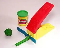
Extrusion is the process of creating an object with a fixed cross-sectional profile. OpenSCAD provides two commands to create 3D solids from a 2D shape: linear_extrude() and rotate_extrude().
Linear extrusion is similar to pushing clay through a die with a profile shape cut through it.
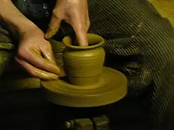
Rotational extrusion is similar to the process of applying a profile to clay spinning on a potter's wheel.
Both extrusion methods work on a (possibly disjointed) 2D shape normally drawn in the relevant plane (see below).
linear_extrude() Operator Module
A Linear Extrusion must be given a 2D child object, as in this statement:
linear_extrude( h=2 ) square();
This child object is first projected onto the X-Y plane along the Z axis to create the starting face of the extrusion. The start face is duplicated at the Z position given by the height parameter to create the extrusion's end face. The extrusion is then formed by creating a surface that joins each point along the edges of the two faces.
The 2D shape may be any 2D primitive shape, a 2d polygon, an imported 2D drawing, or a boolean combination of them. The 2D shape may have a Z value that moves it out of the X-Y plane, and it may even be rotated out of parallel with it. As stated above, the extrusion's starting face is the projection of the 2D shape onto the X-Y plane, which, if it is rotated, will have the effect of fore-shortening it normal to the axis of the rotation.
Using a 3D object as the extrusion's child will cause a compile time error. Including a 3D object in a composition of 2D objects (formed using boolean combinations on them) will be detected, the 3D object(s) will be deleted from it and the remaining 2D objects will be the basis for projecting their shape onto the X-Y plane.
Parameters For Linear Extrusion
There are no required parameters. The default operation is to extrude the child by 100 units vertically from the X-Y Plane, centered on the [0,0] origin.
- 1) height
- a non-negative integer, default 100, giving the length of the extrusion
- 2) v - twist axis vector
- a vector of 3 signed decimal values, default [0,0,1], used as an eigen vector specifying the axis of rotation for the twist. [Note: Requires version Development snapshot]
- 3) center
- a boolean, default false, that, when true, causes the resulting solid to be vertically centered at the X-Y plane.
- 4) convexity
- a non-negative integer, default 1, giving a measure of the complexity of the generated surface. See the Section on Convexity later on this page.
- 5) twist
- a signed decimal, default 0.0, specifying how many degrees of twist to apply between the start and end faces of the extrusion. 180 degrees is a half twist, 360 is all the way around, and so on.
- 6) scale
- either : a non-negative, decimal value, default 1.0, minimum 0.0, that specifies the factor by which the end face should be scaled up, or down, in size from that of the start face.
- or : an [x,y] vector that scales the extrusion in the X and Y directions separately.
- 7) slices
- a non-negative integer for the number of rows of polygons that the extr.
- 8) segments
- Similar to slices but adding points on the polygon's segments without changing the polygon's shape.
- h
- a named parameter, synonym to height
- $fn $fs $fa
- Special Parameters - given as named parameters.
Center
This parameter affects only affects the vertical position or the extrusion. Its X-Y position is always that of the projection that sets its starting face.
Scale
This is multiplicative factor that affects the size of extrusion's end face. As such 1.0 means no change, a value greater than one expands the end face, and a value between 0.001 and less than 1 shrinks it. A value of 0.0 causes the end face to degenerate to a point, turning the extrusion into a pyramid, cone, or complex pointy shape according to what the starting shape is.
Using the vector form sets the scale factor in the X and Y directions separately
Twist
Twist is applied, by default, as a rotation about the Z Axis. When the start face is at the origin a twist creates a spiral out of any corners in the child shape. If the start face is translated away from the origin the twist creates a spring shape.
A positive twist rotates clockwise, negative twist the opposite.
Twist Axis Vector
The second parameter is an [x,y,z] eigen vector that specifies the axis of rotation of the applied twist. The ratios of the three dimensional values to their respective coordinate axes specify the tilt away from the default axis, [0,0,1], the Z-Axis. For instance, v=[cos(45),0,1] tilts the extrusion at 45 degrees to the X axis.
The start and end faces are always normal to the Z-axis, even when the twist axis is tilted. The extruded and twisted surfaces are thus distorted from what might be expected in an extruded shape. The more expected result may be achieved by applying a rotation to then twisted extrusion on the Z Axis to tilt it into the desired position.
$fn, $fa, $fs Special Parameters
The special variables must be given as named parameters and are applied to the extrusion, overriding the global setting. When the same special variables are set on the base shape its values override their use as parameters on the extrusion.
Extrusion From Imported DXF
Example of linear extrusion of a 2D object imported from a DXF file.
linear_extrude(height = fanwidth, center = true, convexity = 10)
   import (file = "example009.dxf", layer = "fan_top");

A Unit Circle with No Twist
Generate an extrusion from a circle 2 units along the X Axis from the origin, centered vertically on the X-Y plane, with no twist. The extrusion appears to have a pentagonal cross-section because the extrusion's child is a 2D circle with the default value for $fn.
linear_extrude(height = 10, center = true, convexity = 10, twist = 0)
    translate([2, 0, 0])
        circle(r = 1);

A Unit Circle Twisted Left 100 Degrees
The same circle, but now with 100 degrees of counter-clockwise twist.
linear_extrude(height = 10, center = true, convexity = 10, twist = -100)
    translate([2, 0, 0])
        circle(r = 1);

A Unit Circle Twisted Right 100 Degrees
The same circle, but now with 100 degrees of clockwise twist.
linear_extrude(height = 10, center = true, convexity = 10, twist = 100)
    translate([2, 0, 0])
        circle(r = 1);

A Unit Circle Twisted Into a Spiral
The same circle, but made into a spiral by 500 degrees of counter-clockwise twist.
linear_extrude(height = 10, center = true, convexity = 10, twist = -500)
    translate([2, 0, 0])
        circle(r = 1);
Center
With center=false, the default, the extrusion is based on the X-Y plane and rises up in the positive Z direction.

When true it is centered vertically at the X-Y plane, as seen here:
Mesh Refinement
The slices parameter defines the number of intermediate points along the Z axis of the extrusion. Its default increases with the value of twist. Explicitly setting slices may improve the output refinement. Additional the segments parameter adds vertices (points) to the extruded polygon resulting in smoother twisted geometries. Segments need to be a multiple of the polygon's fragments to have an effect (6 or 9.. for a circle($fn=3), 8,12.. for a square() ).

linear_extrude(height = 10, center = false, convexity = 10, twist = 360, slices = 100)
translate([2, 0, 0])
circle(r = 1);
The special variables $fn, $fs and $fa can also be used to improve the output. If slices is not defined, its value is taken from the defined $fn value.

linear_extrude(height = 10, center = false, convexity = 10, twist = 360, $fn = 100)
translate([2, 0, 0])
circle(r = 1);
Scale
Scales the 2D shape by this value over the height of the extrusion. Scale can be a scalar or a vector:
 linear_extrude(height = 10, center = true, convexity = 10, scale=3)
 translate([2, 0, 0])
 circle(r = 1);

 linear_extrude(height = 10, center = true, convexity = 10, scale=[1,5], $fn=100)
 translate([2, 0, 0])
 circle(r = 1);

Note that if scale is a vector, the resulting side walls may be nonplanar. Use twist=0 and the slices parameter to avoid asymmetry.
 linear_extrude(height=10, scale=[1,0.1], slices=20, twist=0)
 polygon(points=[[0,0],[20,10],[20,-10]]);
Using with imported SVG
A common usage of this function is to import a 2D svg
 linear_extrude(height = 10, center = true)
 import("knight.svg");
rotate_extrude() Operator Module
Rotational extrusion spins a 2D shape around the Z-axis to form a solid which has rotational symmetry. One way to think of this operation is to imagine a Potter's wheel placed on the X-Y plane with its axis of rotation pointing up towards +Z. Then place the to-be-made object on this virtual Potter's wheel (possibly extending down below the X-Y plane towards -Z). The to-be-made object is the cross-section of the object on the X-Y plane (keeping only the right half, X >= 0). That is the 2D shape that will be fed to rotate_extrude() as the child in order to generate this solid. Note that the object started on the X-Y plane but is tilted up (rotated +90 degrees about the X-axis) to extrude.
Since a 2D shape is rendered by OpenSCAD on the X-Y plane, an alternative way to think of this operation is as follows: spins a 2D shape around the Y-axis to form a solid. The resultant solid is placed so that its axis of rotation lies along the Z-axis.
Just like the linear_extrude, the extrusion is always performed on the projection of the 2D polygon to the XY plane. Transformations like rotate, translate, etc. applied to the 2D polygon before extrusion modify the projection of the 2D polygon to the XY plane and therefore also modify the appearance of the final 3D object.
- A translation in Z of the 2D polygon has no effect on the result (as also the projection is not affected).
- A translation in X increases the diameter of the final object.
- A translation in Y results in a shift of the final object in Z direction.
- A rotation about the X or Y axis distorts the cross section of the final object, as also the projection to the XY plane is distorted.
Don't get confused, as OpenSCAD displays 2D polygons with a certain height in the Z direction, so the 2D object (with its height) appears to have a bigger projection to the XY plane. But for the projection to the XY plane and also for the later extrusion only the base polygon without height is used.
You cannot use rotate_extrude to produce a helix or screw thread. Doing this properly can be difficult, so it's best to find a thread library to make them for you.
The 2D shape must lie completely on either the right (recommended) or the left side of the Y-axis. More precisely speaking, every vertex of the shape must have either x >= 0 or x <= 0. If the shape spans the X axis a warning appears in the console windows and the rotate_extrude() is ignored. If the 2D shape touches the Y axis, i.e. at x=0, it must be a line that touches, not a point, as a point results in a zero thickness 3D object, which is invalid and results in a CGAL error. For OpenSCAD versions prior to 2016.xxxx, if the shape is in the negative axis the resulting faces are oriented inside-out, which may cause undesired effects.
Usage
rotate_extrude(angle = 360, start=0, convexity = 2) {...}

In 2021.01 and previous, you must use parameter names due to a backward compatibility issue.
- convexity : If the extrusion fails for a non-trival 2D shape, try setting the convexity parameter (the default is not 10, but 10 is a "good" value to try). See explanation further down.
- angle [Note: Requires version 2019.05] : Defaults to 360. Specifies the number of degrees to sweep, starting at the positive X axis. The direction of the sweep follows the Right Hand Rule, hence a negative angle sweeps clockwise.
- start [Note: Requires version Development snapshot] : Defaults to 0 if angle is specified, and 180 if not. Specifies the starting angle of the extrusion, counter-clockwise from the positive X axis.
- $fa : minimum angle (in degrees) of each fragment.
- $fs : minimum circumferential length of each fragment.
- $fn : fixed number of fragments in 360 degrees. Values of 3 or more override $fa and $fs
- $fa, $fs and $fn must be named parameters. click here for more details,.
Rotate Extrude on Imported DXF
rotate_extrude(convexity = 10)
   import (file = "example009.dxf", layer = "fan_side", origin = fan_side_center);
Examples
→
A simple torus can be constructed using a rotational extrude.
rotate_extrude(convexity = 10)
    translate([2, 0, 0])
        circle(r = 1);
Mesh Refinement
→
Increasing the number of fragments composing the 2D shape improves the quality of the mesh, but takes longer to render.
rotate_extrude(convexity = 10)
    translate([2, 0, 0])
        circle(r = 1, $fn = 100);
→
The number of fragments used by the extrusion can also be increased.
rotate_extrude(convexity = 10, $fn = 100)
    translate([2, 0, 0])
        circle(r = 1, $fn = 100);
Using the parameter angle (with OpenSCAD versions 2016.xx), a hook can be modeled .
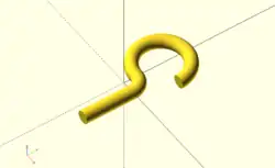
eps = 0.01;
translate([eps, 60, 0])
    rotate_extrude(angle=270, convexity=10)
        translate([40, 0]) circle(10);
rotate_extrude(angle=90, convexity=10)
    translate([20, 0]) circle(10);
translate([20, eps, 0])
    rotate([90, 0, 0]) cylinder(r=10, h=80+eps);
Extruding a Polygon
Extrusion can also be performed on polygons with points chosen by the user.
Here is a simple polygon and its 200 step rotational extrusion. (Note it has been rotated 90 degrees to show how the rotation appears; the rotate_extrude() needs it flat).
rotate([90,0,0]) polygon( points=[[0,0],[2,1],[1,2],[1,3],[3,4],[0,5]] );
rotate_extrude($fn=200) polygon( points=[[0,0],[2,1],[1,2],[1,3],[3,4],[0,5]] );
→ →
→
For more information on polygons, please see: 2D Primitives: Polygon.
Orientation
If you're making a round 360 degree extrusion, it doesn't matter where it starts. If, on the other hand, you're using $fn to make an extrusion with some specific number of sides, it can matter. With an odd number of sides, there will be a vertex on either the left or the right, and a side opposite it.
With angle not specified, the extrusion starts along the negative X axis, to the left of the origin. With an odd number of sides, there is a vertex on the left and a side on the right. (Note that this is inconsistent with the behavior for angle less than 360, and with the behavior for circle and other round primitives.)
With angle specified, and not equal to 360, the extrusion starts along the positive X axis, to the right of the origin.
For 2021.01 and earlier, if angle is equal to 360, the extrusion starts along the negative X axis, as for angle not being specified.
For the development snapshot, if angle is 360, the extrusion starts along the positive X axis, as for other cases where angle is specified. Explicitly specifying angle=360 thus yields results consistent with other round primitives.
A future release may change this behavior so that when angle is not specified the extrusion starts along the positive X axis, making all of these cases consistent.
start directly controls the start point. [Note: Requires version Development snapshot]
Description of extrude parameters
Parameters Used In All Extrusions
- convexity
- an integer that works as a measure of complexity based on the maximum number of sides a ray might penetrate as it passes through a shape.
For instance, the convexity of a sphere is one and the convexity of a torus is two. From any point of view there is only a single surface showing for a sphere. But with a torus a given pixel may be showing the front most face, the back part of the doughnut, or the background. Setting convexity greater than the default 1 informs the renderer of the need to be more careful in its work.
Arbitrarily setting convexity to 10 should solve most preview rendering issues, at the expense of slowing preview rendering. When a model has several convoluted shapes values more than 15 can slow rendering to the point of freezing the application.
The issue of Convexity is an issue in Preview Rendering.
Parameters For Linear Extrusion
- height
- a non-negative integer, default 100, giving the length of the extrusion
- center
- a boolean, default false, that, when true, causes the resulting solid to be vertically centered at the X-Y plane.
- twist
- a signed decimal, default 0.0, specifying how many degrees of twist to apply between the start and end faces of the extrusion
- scale
- a non-negative, decimal value, default 1.0, greater than 0.0, that specifies the factor by which the end face should be scaled up, or down, in size from that of the start face.
- a vector containing these values in this order
- [
- slices
- a non-negative integer value that acts on the extruded surface as $fn does, but which is not applied to the child 2D shape.
- segments
- Similar to slices but adding points on the polygon's segments without changing the polygon's shape.
- $fn
- the special variable but applied only to the extrusion
- $fs
- the special variable but applied only to the extrusion
- $fa
- the special variable but applied only to the extrusion
- ]
Note
- centering the extrusion only affects its vertical position. Its X-Y position is always set by its starting face.
- A Scale Factor greater than one increases the size of the extrusion's end face, while a value greater than 0.0 and less than 1 shrink it. A value of 0.0 causes the end face to degenerate to a point, turning the extrusion into a pyramid, cone, or complex pointy shape according to what the starting shape is.
With the import() and extrusion modules it is possible to convert 2D objects read from DXF files to 3D objects. See also 2D to 3D Extrusion.
Linear Extrude
Example of linear extrusion of a 2D object imported from a DXF file.
linear_extrude(height = fanwidth, center = true, convexity = 10)
   import (file = "example009.dxf", layer = "fan_top");
Rotate Extrude
Example of rotational extrusion of a 2D object imported from a DXF file.
rotate_extrude(convexity = 10)
   import (file = "example009.dxf", layer = "fan_side", origin = fan_side_center);